
Leon Mk1
|
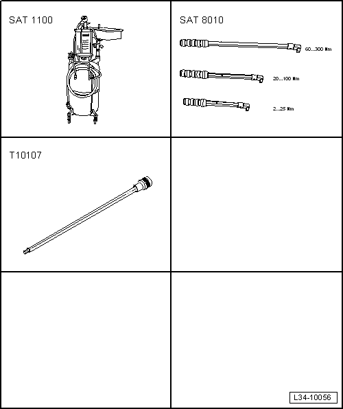
| Special tools and workshop equipment required |
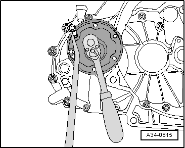
| t | Extractor -SAT 1100-, see equivalent → Anchor |
| t | Torque wrench kit -SAT 8010-, see equivalent → Anchor |
| t | Socket and key -T10107- |
|
|
|
|
|
|
|
|

|
|
|
|
|
|
|
 Note
Note
|
|
|
|
|
|
 Caution
|
|
|
|
|
|
Note
Note
Note |
|
|
|
|
|
|
|
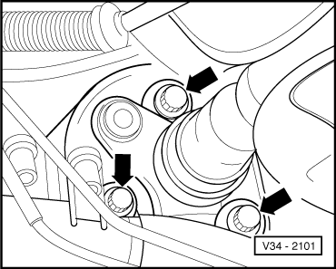
| Component | Nm |
| Heat shield for drive shaft to bevel box | 25 |