seat Workshop Repair Guides

SEAT Workshop Service and Repair Manuals

Cleaning refrigerant circuit of impurities using R134a refrigerant > < Possible complaints regarding the refrigerant circuit
Description and operation of the cleaning stationSAT 4011
Description and operation of the cleaning station -SAT 4011-
General information: → Service Manual for the cleaning station
Remove the refrigerant from the circuit using the a/c loading station -SAT 4006D-.
The cleaning station -SAT 4011- has a control panel with two areas:
  WARNING
t  Use only pressure reduction valves for nitrogen bottles (minimum operating pressure 8 bars and max. operating pressure 12 bars).
t  The safety regulations must be closely observed for the correct use of the unit.
   
Zone -A- of the panel for cleaning with nitrogen:
1 - Nitrogen input tap to component to be cleaned
Check that the tap on the external nitrogen tank is open, and there is a maximum output pressure of 12 bar.
Open the tap -IN- until the manometer shows a pressure reading of 12 bar, then close the tap. Once pressurised, if the pressure has not changed after 10 minutes, then there are no leaks.
2 - Nitrogen output tap from component to be cleaned
Despressurise the circuit by opening the output tap -OUT-.
3 - Manometer for nitrogen pressure in the circuit
Operating pressure for circuit flush or purge -Min.÷Max-: -8-12 bar-
If the manometer reading changes, the circuit is not leakproof.
Zone -A- of the panel for cleaning with solvent:
1 - Solvent viewing window
It is possible to see through the window whether the solvent is clean or carrying particles.
If it is very dirty it should be dismounted and clean
2 - Tap for circuit flush or purge -Flush- o -Purge-
The purge tap is closed when no more particles are observed in the solution.
In position -B- or -C- the vacuum pump will start to operate to fill the machine with solvent.
The numerical field is the operating range for the flushing operation; Position -2- leave in this position for ten minutes, then continue with Position -5-, again for at least 10 minutes, then continue with Position -0-. The flushing procedure is then concluded properly.
3 - Manometer for the circuit wash or purge pressure
Operating pressure for circuit flush or purge -Min.÷Max-: -6-8 bar-
  E00-10265
Connection area for the solvent inlet / outlet: Reverse side
1 - Air/solvent separator
Solvent should be treated as hazardous waste, and the regulations applicable in your region or country must be observed.
2 - Solvent input to component or circuit to be cleaned
Solvent input with a fluid impulse system.
3 - Solvent output from the component or circuit which is being cleaned
Circuit closed, in operating position
4 - Return to tank tap
On completion of the operation the solvent must be drained from the machine to the recipient.
  E00-10266
Connection area for the nitrogen inlet / outlet: Reverse side
1 - Nitrogen input to circuit or component
Execution of nitrogen sweep at pressure between -6÷12 bar- in order to drag away any possible traces of solvent and humidity that may remain in the component or circuit after the purge phase.
2 - Nitrogen output from circuit or component
Circuit closed, in operating position
  E00-10267
Connection area for inlet / outlet for filling: Side of the unit
1 - Level of solvent
Do not fill with more than 20 litres, this could cause malfunctions.
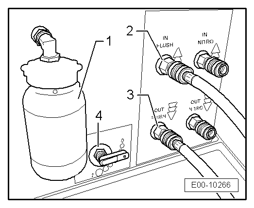
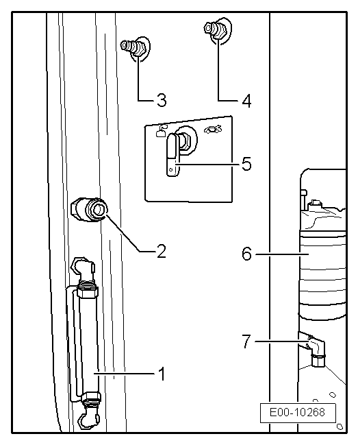
2 - Solvent filling and drainage connection
Recommended minimum operating level -10 litres-.
Solvent should be treated as hazardous waste, and the regulations applicable in your region or country must be observed.
On completion of the operation the solvent must be drained from the machine to the recipient.
3 - Compressed air connection
Limit the input pressure to an operating pressure between -min. 5 bar- and -max. 8 bar-.
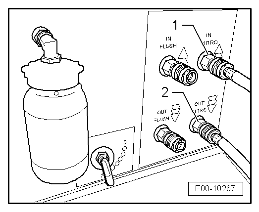
4 - Input connection from nitrogen tank to equipment
Check that the tap on the external nitrogen tank is open, and there is a maximum output pressure reading on the pressure control of -12 bar-.
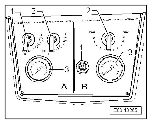
5 - Operating zone selector switch
The switch has three positions: -CHARGE- to start the vacuum pump and fill the machine with solvent.
-STOP- when it is not to be used, disconnected from the compressed air circuit.
-WORK- operating or wash position.
6 - External filter
Replace filter regularly, at least every 10 times a not very dirty circuit is cleaned, and every 3 washes if the circuits are very dirty.
It should be treated as hazardous waste, and the regulations applicable in your region or country must be observed.
When replacing, check that it is not pressurised, that is, it is not under pressure and the machine is disconnected from the compressed air installation.
7 - Nitrogen discharge connection
The sweep stage is not finished until nitrogen also comes out through the nitrogen discharge connection.
  E00-10268
Input and output hose connections:
1 - Red hose connection with the tool
connect to rear of equipment -OUT NITRO- and to the service connection of the corresponding system to be cleaned, low pressure end.
Ensure that cone is connected properly, leakage is possible if installed incorrectly. Replace rubber cone when worn.
2 - Black hose connection with the tool
connect to rear of equipment -IN NITRO- and to the service connection of the corresponding system to be cleaned, high pressure end.
Ensure that cone is connected properly, leakage is possible if installed incorrectly. Replace rubber cone when worn.
  E00-10269

Cleaning refrigerant circuit of impurities using R134a refrigerant > < Possible complaints regarding the refrigerant circuit