
Leon Mk1
| Dismantling and assembling pistons and conrods |
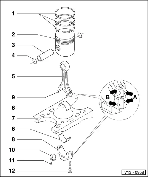
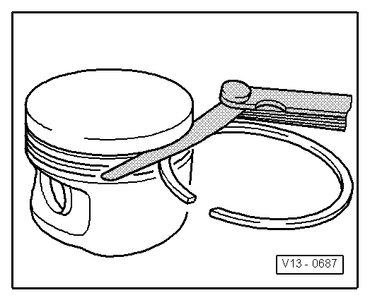
| 1 - | Piston rings |
| q | Remove and install with piston ring pliers |
| q | Offset gaps by 120° |
| q | Check clearance |
| q | “TOP” faces towards piston crown |
| q | Checking ring gap → Fig. |
| q | Checking ring to groove clearance → Fig. |
| 2 - | Piston |
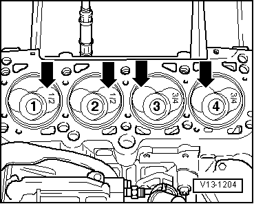
| q | Mark installation position and correspondence with the cylinder |
| q | Installation position and piston/cylinder correspondence → Fig. |
| q | Check piston position at TDC → Chapter |
| q | Arrow on piston crown points to pulley end |
| 3 - | Piston pin |
| q | Remove and install with -U-20008- tool |
| q | Pin diameter = 26 mm |
| 4 - | Safety washer |
| 5 - | Conrod |
| q | Only renew as a set |
| q | Mark correspondence with cylinder number -A- |
| q | The marks -B- must point to the distribution side |
| q | Conrod length = 144 mm |
| 6 - | Conrod bearing shell |
| q | Note the fitting position |
| q | Do not interchange used bearing shells |
| q | Make sure the retaining lugs are correctly seated. |
| q | Axial clearance: Maximum: 0.37 mm |
| q | Check radial clearance with Plastigage: Maximum: 0.08 mm |
| q | Do not rotate the crankshaft when checking the radial clearance |
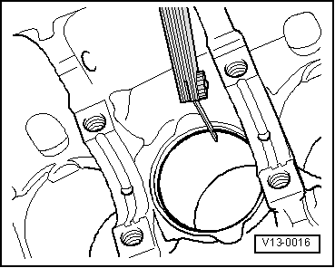
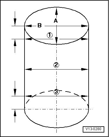
| 7 - | Cylinder block |
| q | Checking cylinder bores → Fig. |
| q | Piston and cylinder dimensions → Chapter. |
| 8 - | Conrod bearing cap |
| q | The marks -B- must point to the distribution side |
| 9 - | Dowel peg |
| q | They should house firmly in the bearing and not in the cap |
| 10 - | Oil injector |
| q | For piston cooling |
| 11 - | 10 Nm |
| q | Use suitable sealant for fitting |
| 12 - | 30 Nm + 1/4 turn (90°) |
| q | Renew |
| q | Oil the threads and contact surface |
| q | To measure the radial clearance use an old bolt |
| Gap | |||
| Piston ring | New | Wear limit | |
| 1st compression ring | mm | 0.20 … 0.40 | 1.0 |
| 2nd compression ring | mm | 0.20 … 0.40 | 1.0 |
| Oil scraper ring | mm | 0.25 … 0.50 | 1.0 |
|
|
| Clearance | |||
| Piston ring | New | Wear limit | |
| 1st compression ring | mm | 0.06 … 0.09 | 0.25 |
| 2nd compression ring | mm | 0.05 … 0.08 | 0.25 |
| Oil scraper ring | mm | 0.03 … 0.06 | 0.15 |
 Note!
Note!
|
|
Note!
|
|