Leon Mk1
|
|
|
|
|
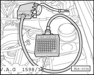
| Test box -V.A.G 1598/18-, socket | ||
| 19 + 39, 39 + 45, 19 + 45 | ||
| Specification: ∞ Ω |
|
|
|
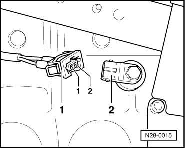
| Contact | Test box -V.A.G 1598/18-, socket | |
| 1 | 39 | |
| 2 | 19 | |
| Wire resistance: 1,5 Ω max. | ||
|

|
|
|
|
|
| Test box -V.A.G 1598/18-, socket | ||
| 19 + 39, 39 + 45, 19 + 45 | ||
| Specification: ∞ Ω |
|
|
|
| Contact | Test box -V.A.G 1598/18-, socket | |
| 1 | 39 | |
| 2 | 19 | |
| Wire resistance: 1,5 Ω max. | ||
|