| –
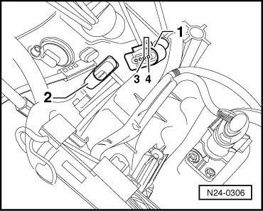
| Pull connector -1- off intake manifold pressure sender -G71- with intake air temperature sender -G42--2- (engine stalls). |
| –
| Press keys 0 and 6 for the “End output” function and confirm input with the Q key. |
| –
| Renew the intake manifold pressure sender -G71- with intake air temperature sender -G42--2-, → Item. |
| –
| Press keys 0 and 6 for the “End output” function and confirm input with the Q key. |
| –
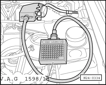
| Remove the connector of the engine control unit. |
| –
| Check the wiring to the control unit connector at 4-pin connector, contact 4, for short circuits to wire contact 3 and battery positive. |
| If no wiring fault is detected: |
|
|

|