
Leon Mk1
|

| Special tools and workshop equipment required |
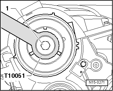
| t | Counterhold tool -T10051- |
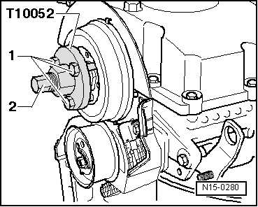
| t | Extractor -T10052A- |
| t | Torque wrench -SAT 8010- |
| t | Silicone sealant → Spare parts catalogue |
|
|
|
|
|
 Note
Note
Note
Note |
|
Note
|
|
|
|
|
|
Note
Note
|
|