| –
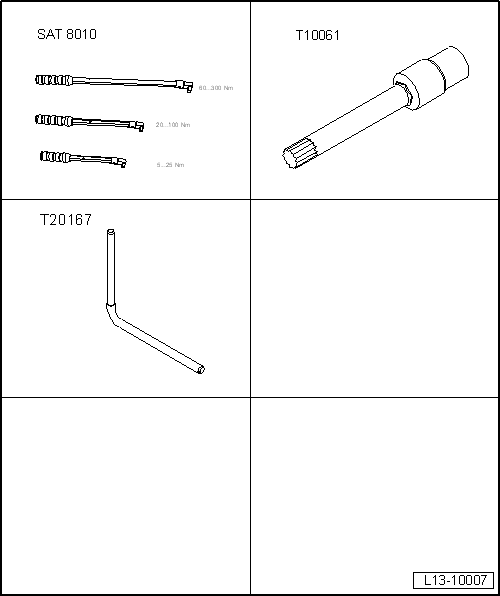
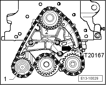
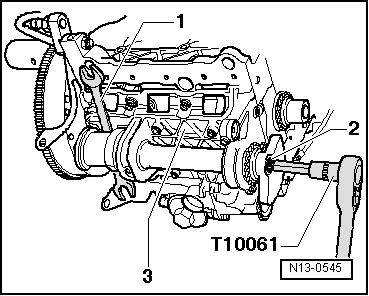
| Secure the balance shaft as shown in the illustration using the wrench -1- (e/c 24/27). |

Note | The attachment bolt -2- for the counterweight should only be loosened, do not completely undo. |
| –
| Loosen the securing bolt -2- for the counterweight, using the wrench -T10061- . |
| –
| Unscrew the shaft bracket -3- from the engine block and remove it along with the balance shaft. |
| –
| Place the shaft bracket on a clean surface. |
| –
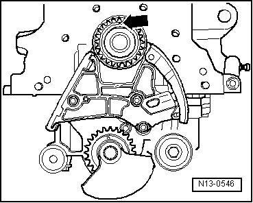
| Extract the securing bolt -2- from the counterweight. |
| –
| Remove the counterweight and pinion from the balance shaft. |
| –
| Rotate the balance shaft until it can be removed from its allotment. |
| –
| Apply oil to the bearing surfaces in the balance shaft allotment. |
| –
| Fit the balance shaft in its allotment. |
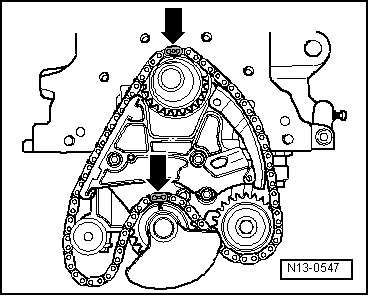
Note | The installation of the pinion and the counterweight is only possible in one position. |
| –
| Fit the pinion and the counterweight on to the balance shaft. |
| –
| Manually tighten the attachment bolt for the counterweight and pinion. |
| –
| Manual tighten the shaft bracket to the engine block so that there is no play. |
Note | t
| When fitting the shaft bracket, ensure that the adjustment sleeve is fitted to the engine block and that the O-ring is on the shaft bracket. |
| t
| Fit the shaft bracket so that on the pulley side, it is flush with the outside edge of the engine block. |
| –
| Tighten the shaft bracket with the balance shaft to the engine block and tighten to: 20 Nm. |
| –
| Ensure that the shaft bracket on the pulley side is flush with the outside edge of the engine block. |
Note | The wrench must be centred with respect to the counterweight of the balance shaft and perpendicular with respect to the balance shaft. |
|
|
|