
Leon Mk1
|
|
|
|
|
 Note
Note
Note
|
|
|
|
|
|
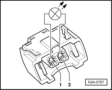
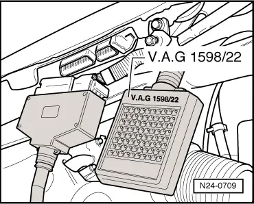
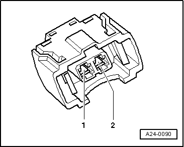
| Cyl. | Injector connector, contact | Test box -V.A.G 1598/22-, socket |
| 1 | 2 | 79 |
| 2 | 2 | 59 |
| 3 | 2 | 73 |
| 4 | 2 | 65 |
| Specification: 1.5 Ω max. | ||
|
|
|