seat Workshop Repair Guides

SEAT Workshop Service and Repair Manuals

Support elements with hydraulic compensation: verification > < Removing and installing camshaft
Replacing valve shaft seals.
t  Work sequence → Anchor
t  Tightening torques → Anchor
   
Consult the equivalence table for tools and equipment according to applicability between Seat / VW / Audi / Skoda → Chapter
Special tools and workshop equipment required
t  Hose clamp -VW 653/3-, see equivalent → Anchor
t  Spanner -3122B-, see equivalent → Anchor
t  Extractor -3364-, see equivalent → Anchor
t  Hose clamp -3365-, see equivalent → Anchor
t  Valve installation kit -VAS 5161- with guide plate -VAS 5161/20-, see equivalent → Anchor

   
t  Sparkplug pliers -VAG 1922-, see equivalent → Anchor
  W00-1100
t  Torque wrench -VAG 1331-, see equivalent → Anchor.
Work sequence
–  Remove camshaft → Chapter.
  Note
Use waterproof felt-tip pen to mark the assignment of the roller rocker fingers.
–  Remove roller rocker arms and place on a clean surface. Put down in the sequence of their installation position (do not interchange the position of the roller rocker arms).
–  Remove sparkplug connector with sparkplug pliers -VAG 1922-.
–  Unscrew the spark plugs using spark plug spanner -3122B-.
–  Set piston of the respective cylinder to „bottom dead centre“.
  W00-0427
–  Place guide plate -VAS 5161/20- onto cylinder head.
l  The marking „OBEN“ (TOP) faces upwards.
–  Fasten guide plate -VAS 5161/20- with two nuts.
–  Screw holding device -VW 653/3- into sparkplug thread and connect hose to compressed air.
l  Minimum pressure: 6 bar
–  Position punch -VAS 5161/3- on guide plate and free stuck valve keeper with plastic mallet.
  A15-10170
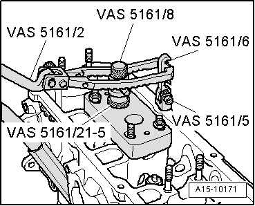
–  Screw snap-in device -VAS 5161/6- with engaging forks -VAS 5161/5- into guide plate -VAS 5161/20-.
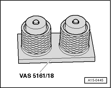
–  Slide the knurled spacer ring (height: 8,4 mm) -VAS 5161/17- onto the assembly cartridge -VAS 5161/8-.
–  Attach pressure fork -VAS 5161/2- to snap-in device -VAS 5161/6- and push assembly cartridge down.
–  At the same time, turn knurled screw of assembly cartridge clockwise until tips engage in valve cotters.
–  Move the knurled bolt lightly from side to side. In this way the valve cotter pins are separated by the pressure and fit into the cartridge.
–  Release pressure fork.
–  Remove the assembly cartridge with a knurled spacer ring, valve head and valve spring.
  A15-10171
–  Extract the valve stem seals with the extractor -3364- .
  Note
  A15-10155
A plastic sleeve -A- is included with the new valve stem oil seals.
–  Fit plastic sleeve -A- onto valve stem to prevent damage to new valve stem oil seal -B-.
–  Lightly lubricate sealing lip of valve stem oil seal.
–  Slip valve stem oil seal over plastic sleeve.
–  Carefully press valve stem oil seal onto valve guide using valve stem seal fitting tool -3365-.
–  Remove plastic sleeve.
  N15-0406
–  If valve cotters have been removed from assembly cartridge, they need to be put into insertion device -VAS 5161/18- first.
  Note
The larger diameter of the valve cotters face upwards.
–  Press assembly cartridge onto insertion device from above and take up valve cotters.
  A15-0445
–  Re-insert assembly cartridge with knurled spacer ring (height: 8.4 mm) into guide plate.
–  Push pressure fork down and pull knurled screw upwards while turning screw in both directions - this will insert the valve cotters.
–  Release pressure fork with knurled screw still in pulled position.
–  Insert bucket tappets.
Assembly is carried out in the reverse order to removal; note the following:
–  Install the camshaft → Chapter
  Note
t  After installing the camshaft wait for approx. 30 minutes before starting engine. The hydraulic elements should be allowed to sit in place (if not, the valves may press on the cylinder).
t  After working on the valve gear, turn the engine carefully at least 2 rotations to ensure that none of the valves make contact when the starter is operated.
Tightening torques
  A15-10171
Components:Nm
Spark plugs in cylinder head30


Support elements with hydraulic compensation: verification > < Removing and installing camshaft