seat Workshop Repair Guides

SEAT Workshop Service and Repair Manuals

Engine lubrication > < Removing and installing cylinder head
Removing and installing Hall senderG40
Removing and installing Hall sender -G40-
t  Removing → Anchor
t  Installing → Anchor
Consult the equivalence table for tools and equipment according to applicability among Seat / VW / Audi / Skoda → Chapter.
   
Special tools and workshop equipment required
t  Hose clamp -3359-, see equivalent → Anchor
t  Hose clamp -T10050-, see equivalent → Anchor
t  counterhold -T10172-, see equivalent → Anchor
t  Spanner -T10264-, see equivalent → Anchor
t  Hose clamp -T10265-, see equivalent → Anchor

   
Removing
–  Disconnect the engine cover-arrow-.
  E10-10060
–  Loosen quick-type locks -1 and 2-, and remove front noise insulation.
–  Remove the front bumper trim → Rep. gr.63.
–  Move lock carrier to service position → Rep. gr.50.
  A10-1320
–  Open clips -arrows- and remove toothed belt cover.
–  Remove the Poly V-belt → Chapter.
–  Remove vibration damper → Chapter.
  A10-11056
–  Place the engine on the TD and stop the crankshaft sprocket with the Crankshaft immobiliser -T10050-. To do so, insert the counterhold in the gear teeth at the front of the timing belt wheel. Toothed segment of camshaft must be at »12« o'clock position.
  Note
The mark of the crankshaft sprocket -2- must correspond with the mark of the Support tool -T10050--1-. The pin of the crankshaft immobiliser -T10050- must fit in the sealing flange hole.
  A13-0350
–  Loosen the bolts -1- that hold the camshaft wheel.
  N15-0232
–  Unscrew mounting bolts -1- for high pressure pump sprocket.
  A13-10647
–  Remove the securing nut of the tensioning roller -1- and turn the eccentric adjuster of the tensioning roller with the Socket wrench -T10264- in the anti-clockwise direction -Arrow- till the tensioning roller can be locked with the Locking tool -T10265-.
  N15-10332
–  Next turn the off-centre adjustment in the direction of the -arrow- as far as possible and hand tighten the fastening nut -1-.
–  Remove the toothed belt from the idler roller and the high pressure pump.
  N15-10333
–  Separate connector Hall sender -G40--arrow-.
–  Take the connection out from its bracket.
  N15-10416
–  Remove the Hall sender -G40--Arrow-.
  A23-0257
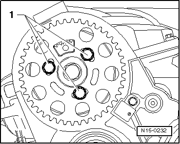
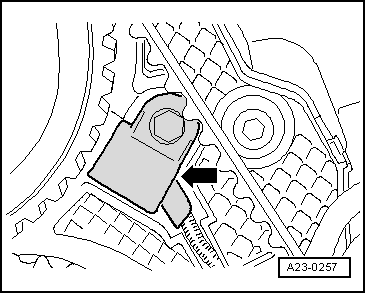
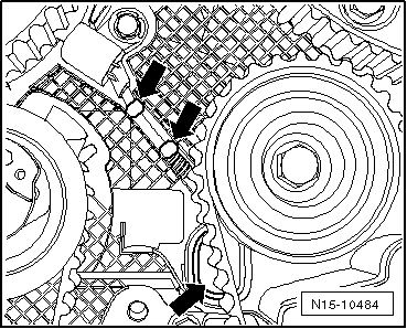
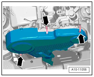
–  Release the latches with a screwdriver and remove the cover from the repair opening -Arrows-.
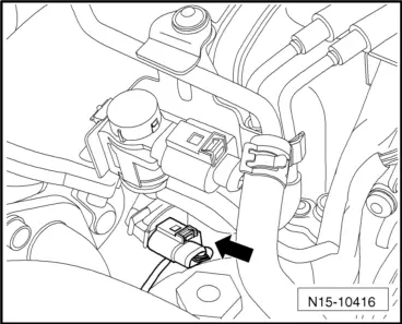
–  Remove the Hall sender -G40- from the cylinder head and guide its connection through the opening in the toothed belt cover provided for repair purposes.
Installing
Installation is in the reverse sequence of removal. In the process, note the following:
t  Cover the toothed belt cover opening, which is provided for repair purposes, with a rubber cover. See → Spare parts catalogue.
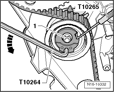
–  Fit the toothed belt and set the valve timings → Anchor.
  N15-10484

Engine lubrication > < Removing and installing cylinder head