seat Workshop Repair Guides

SEAT Leon Workshop Service and Auto Repair Manuals

Cylinder head > < Removing and installing camshaft oil seal
Cylinder head covers: removing and installing
t  Removing → Anchor.
t  Installing → Anchor.
Consult the equivalence table for tools and equipment according to applicability among Seat / VW / Audi / Skoda → Chapter.
Special tools and workshop equipment required
   
t  Torque wrench (5 - 50 Nm) -V.A.G 1331-, see equivalent → Anchor
  W00-0427
t  Base -3314-, see equivalent → Anchor
  W00-0019
Removing .
–  Remove the engine cover upwards -arrows-.
–  Remove the sound insulation of the injector valves.
  E10-10085
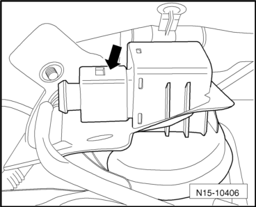
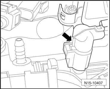
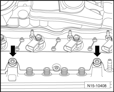
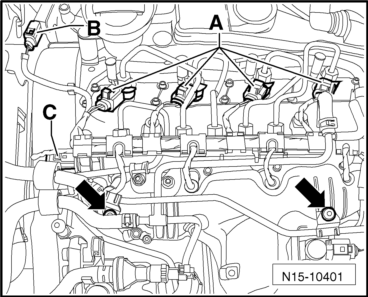
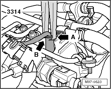
–  Disconnect the plug connector of injector -A- of the exhaust gas pressure sensor 1 -G450--B- and the Common Rail pressure sensor -C-.
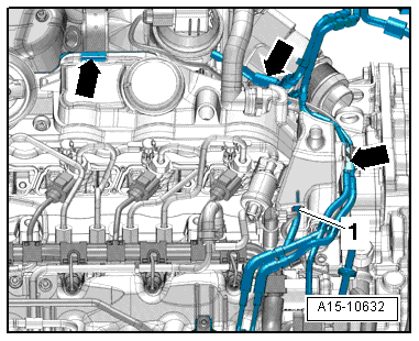
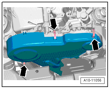
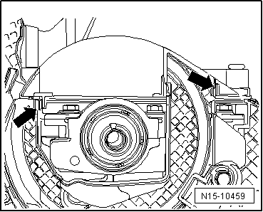
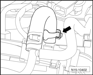
–  Unscrew the fixing bolts of the coolant pipe -arrow- on the intake pipe and and position the pipe in front of the intake pipe.
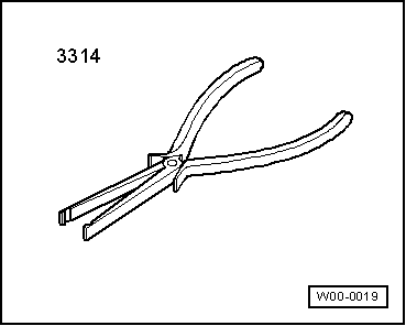
  Caution
Pay particular attention not to damage the wires when removing the connections, because otherwise it would be necessary to replace the entire wiring harness. Do not press pliers -3314- together excessively when removing the connection, because otherwise the bearing supports could be damaged.
  N15-10401
–  Position pliers -3314- with groove -arrow A- on support sleeve shoulder -arrow B- and pull plugs off glow pin plugs.
  M97-0523
–  Unscrew the fixing nuts of the fuel return line on the intake pipe, open the clamp -arrow- and remove the line of the Common Rail.
  N15-10402
–  Remove the connections of the fuel return line from the injectors. For this purpose, push the lugs down by applying a little pressure to the connection and remove the upper element upwards to release it.
  Note
Ensure cleanliness. No dirt must be allowed to enter the return lines or into the open connections on the injectors.
–  Remove entire fuel return line and set it down in front of intake manifold.
  N15-10404
–  Separate the plug connection of the charge pressure actuator position sender -G581--arrow- on the exhaust gas turbocharger and loosen the line from the retainers.
  N15-10406
–  Separate the connector of the regulation valve for fuel pressure -N276--arrow- .
–  Remove the line routing of the common rail and lay to one side.
  N15-10407
–  Remove the vacuum hose -1- from the cylinder head cover.
–  Move electrical wiring and remaining vacuum hoses clear -arrows-.
  A15-10632
–  Hang out the clips -arrows- and remove the upper cover of the toothed belt.
  A10-11056
–  Loosen the breather hose -1- of the crankshaft sump from the cylinder head cover. Press-in the tab for releasing.
  Note
Ignore positions -2- and the -arrows-.
–  Remove the pressure line between the high pressure pump and the common rail.
–  Remove the high pressure line between the common rail and the injectors.
  A21-10337
–  Unscrew the bolts-arrows- and remove the common rail.
–  Remove injectors → Chapter.
  N15-10408
–  Slacken cylinder head cover bolts in the sequence -7 ... 1-.
–  Remove bolts and take off cylinder head cover.
Installing .
Installation is carried out in the reverse order; note the following:
  Note
Renew seal for bolts if damaged.
–  Manually fasten the bolts for the cylinder head cover in the sequence -1 … 7-.
  N15-10414
–  Tighten the bolts to 10 Nm in the following order -1 ... 7-.
–  Make sure that the cylinder head cover has been engaged correctly on the toothed belt guard.
  Note
The figure shows the gear pinion removed from the camshaft.
  N15-10414
–  For this purpose, press the toothed belt guard against the cylinder head cover in the area of the fixings -arrows-, e.g. using a screwdriver until you can hear it engaging.
–  Check that enough free space is left between the hub and the toothed belt guard..
–  Install high-pressure lines → Chapter.
  N15-10459

Cylinder head > < Removing and installing camshaft oil seal