
Leon Mk1
| Compressor: removing and fitting |

| Special tools and workshop equipment required |
| t | Pliers for clamps -VAS 5024A- |
| t | Torque wrench (5...50 Nm) -V.A.G 1331- |
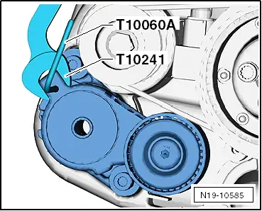
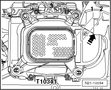
| t | Guide pins -T10341- |
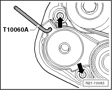
| t | Locking pin -T10060 A- |
|
|
|
|
|
|
|
|
|
|
|
|
|
|
|
|
|
|
|
|
|
|
|
|
|
|
|
|
|
|

|
 Note
Note
|
|
|
|
|
|
|
|
|
|
|
|
Note
|
|
|
|
|
|
 Caution
|
|