seat Workshop Repair Guides

SEAT Workshop Service and Repair Manuals

Coolant pump: Removing and installing > < Diagram of coolant hose connections
Coolant: draining and filling
t  Empty → Anchor
t  Filling → Anchor
Check the tool and equipment equivalence table according to the applicability between Seat / VW / Audi / Skoda → Chapter
   
Special tools and workshop equipment required
t  Refractometer -T10007A-, see equivalent → Anchor
t  Adapter -VAG 1274/8-, see equivalent → Anchor
t  Coolant charger -VAS 6096-, see equivalent → Anchor
t  Collecting tray -VAS 6208-, see equivalent → Anchor
t  Pliers for spring-loaded band-type clamps -VAS 6499-, see equivalent → Anchor
t  Engine sealing plug set -VAS 6122-, see equivalent → Anchor

Draining
  Note
Collect drained coolant in a clean container for re-use or disposal.
  WARNING
Hot vapour/hot coolant may escape when opening expansion tank. Cover cap with cloth and open carefully.
–  Open the cap of the coolant expansion tank.
   
–  Remove the centre noise insulation, fastening points -1 … 3- → Bodywork, exterior fitting work; Rep. Gr.50.
–  Place the drip tray -VAS 6208- under the engine.
  A10-1565
–  Disconnect the coolant hose from the radiator; remove the retaining clamp -arrow- from below.
  A19-10170
–  Detach the outer -1- and inner -2- engine covers, by pulling them evenly upwards.
  E10-10038
–  Remove air intake hose -arrow- from between lock carrier and air filter housing.
  A17-0399
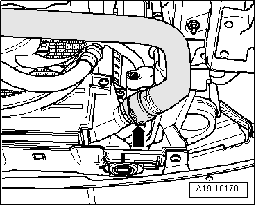
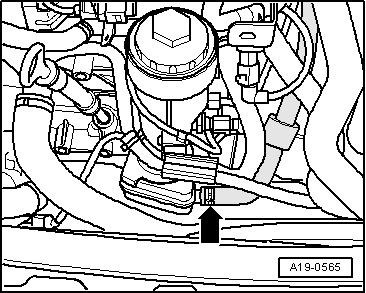
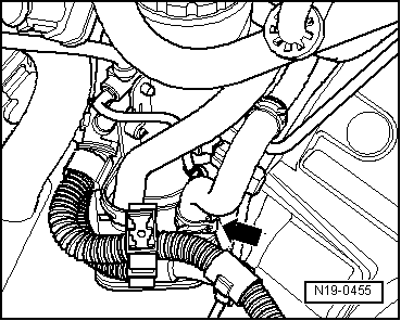
–  Disconnect coolant hose at bottom of the oil radiator -arrow-, and drain off remaining coolant.
Filling
  Note
t  With the range of models later than 2008, only G 12 plus-plus anti-freeze agent must be used according to standard TL VW 774 G.
t  The range of models up to and including 2007 can use Gº12º plus anti-freeze agent, according to TLºVWº774ºF and Gº12º plus-plus, according to TLºVWº774ºG.
t  G 12 plus-plus may never be mixed with G 12 plus coolant additive. Both agents are coloured mauve.
t  “TLºVWº774ºG” or “TLºVWº774ºF” anti-freeze agents prevent damage from rust, freezing or lime sediment, and also raise the boiling point of the coolant. For these reasons, the cooling system must be filled all year round with an anti-freeze and anti-corrosion additive.
t  Thanks to this rise in the boiling point, the coolant guarantees good running, even when the engine undergoes heavy strain, especially in countries with tropical climates.
t  Check that protection against freezing is ensured to approximately -25 °C (down to approx. -35°C in countries with arctic climate).
t  The concentration of the coolant must not be reduced by adding water in summer or in countries with hot climates. The amount of anti-freeze in the coolant must be at least 40 %.
t  If the climate requires a stronger anti-freeze, the anti-freeze agent can be increased, but only up to 60% (anti-freeze protection down to approx. -40ºC). If the proportion is greater, the cooling and anti-freeze protection capacity is reduced.
t  If radiator, heat exchanger, cylinder head or cylinder head gasket has been replaced, do not reuse old coolant.
t  Use refractometer -T10007- to check frost protection of coolant additive “G12+” in cooling system.
t  Replace the seal.
  N19-0455
–  Connect coolant hose on the radiator -arrow-.
  A19-10170
–  Connect coolant hose to the oil cooler -arrow-.
  A19-0565
–  Remove centre noise insulation -fastening points 1 … 3- → Bodywork, exterior fitting work; Rep. Gr.50 .
  A10-1565
–  Fill coolant reservoir -VAS 6096/1- with at least 8 l premixed coolant of the right mixture ratio:
l  “G12+” (40 %) and water (60 %), for a protection to -25 °C
l  “G12+” (50 %) and water (50 %), for a protection to -35 °C
l  “G12+” (40 %) and water (60 %), for a protection to -40 °C
–  Fit adaptor for cooling system tester -V.A.G 1274/8- to the coolant expansion tank.
–  Fit charger -VAS 6096- onto adaptor -V.A.G 1274/8-.
–  Introduce air discharge hose -1- into a small recipient -2-. When flashing off a small quantity of coolant is carried away, which is to be collected.
–  Connect both valves -A- and -B- (lever arm transverse to direction of flow).
–  Connect hose -3- to compressed air.
l  Pressure: 6 … 10 bar
  A19-0351
–  Open valve -B- (lever arm pointing in direction of flow).
The suction jet pump creates a vacuum in the cooling system.
l  The display instrument needle must move to the green area.
–  Also briefly open valve -A- (turn lever in direction of flow) so that the charger -VAS 6096- hose can fill with coolant.
–  Close the valve again -A-.
–  Leave valve -B- open for 2 further minutes.
l  The suction jet pump creates further vacuum in the cooling system.
l  The pointer of the indicator must remain in the green zone.
–  Close valve -B-.
l  The display instrument needle must remain in the green area so that the vacuum in the cooling system is sufficient for the following charge.
If the needle is below the green area, repeat the procedure.
If the vacuum drops the cooling system is leaking.
–  Pull out pressure hose.
–  Open valve -A-.
The vacuum in the cooling system causes the coolant to be drawn out of the cooling system charge unit -VAS 6096/1-; the cooling system is then filled.
  A19-0353
–  Check coolant level and fill coolant up to max. mark.
–  Start engine and run at approx. 2000 rpm for max. 2 minutes and at the same time fill with coolant up to overflow hole on expansion tank.
–  Screw on cap on coolant expansion tank.
–  Run engine until radiator fan cuts-in.
  WARNING
Hot vapour/hot coolant may escape when opening expansion tank. Cover cap with cloth and open carefully.
–  Check coolant level and top-up if necessary.
l  When the engine is at normal operating temperature, the coolant level must be on the max. mark and between the min. and max. marks when the engine is cold.
  A19-0480

Coolant pump: Removing and installing > < Diagram of coolant hose connections