
Leon Mk1
|

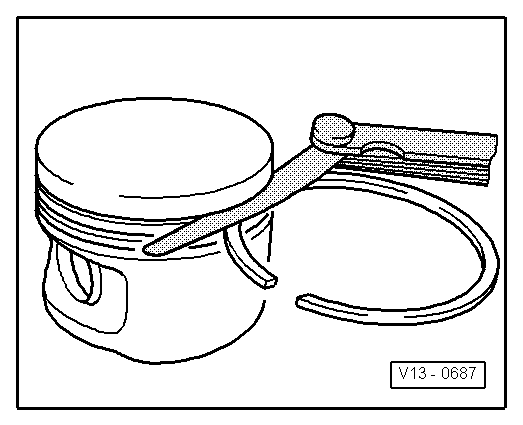
| 1 - | Piston rings |
| q | Displace cutouts 120º |
| q | Remove and install using piston ring pliers. |
| q | The mark “TOP” must face towards piston crown |
| q | Piston ring: Checking end clearance → Fig. |
| q | Groove clearance: check → Fig. |
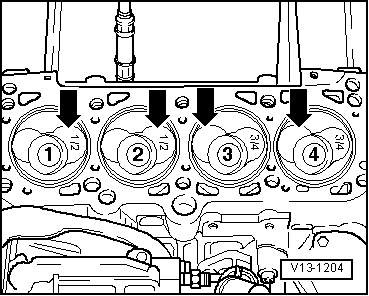
| 2 - | Piston |
| q | With combustion chamber |
| q | Mark installation position and cylinder number. |
| q | Installation position and piston/cylinder correspondence → Fig. |
| q | Arrow on piston crown points to pulley end |
| q | Install using piston ring clamp |
| q | If the piston is scratched, replace it |
| q | Checking piston position at TDC → Chapter |
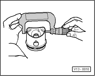
| 3 - | Piston pin |
| q | If difficult to move, heat piston to 60 °C |
| q | Removing and installing with the awl -VW 222- |
| 4 - | Securing ring |
| 5 - | Conrod |
| q | Mark the correspondence to the cylinder -A- using a colour marker |
| q | Installation position: The marks -B- should point towards the pulley |
| q | With ruptured bearing caps |
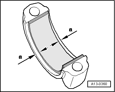
| 6 - | Bearing shell |
| q | Installation position → Fig. |
| q | Note design: Upper half bearing shell (to piston) made from high resistance material. Identification: Black line on the sliding surface in the cutting area |
| q | Do not interchange used bearing shells |
| q | Centrally align bearing shells on insertion |
| q | Check for secure seating. |
| q | Axial play, wear limit: 0.37 mm |
| q | Check the radial play using a Plastigage: Wear limit: 0.08 mm when measuring the radial play, do not rotate the crankshaft |
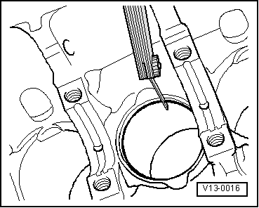
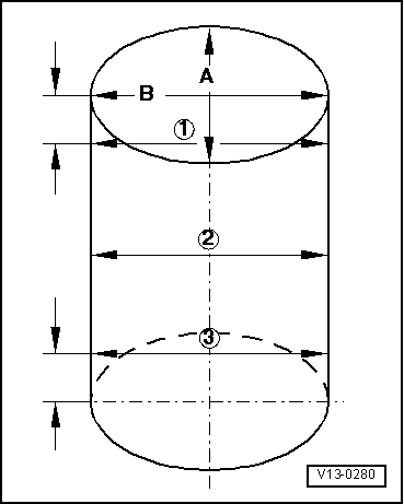
| 7 - | Cylinder block |
| q | Checking cylinder bore → Fig. |
| q | Piston and cylinder dimensions → Chapter |
| 8 - | Conrod bearing cap |
| q | Note fitting position: |
| q | Rods divided by fracturing (cracking) can only be fitted in one position and only with the corresponding conrod |
| 9 - | Oil injection nozzle |
| q | for piston cooling |
| 10 - | Hollow bolt with valve, -25 Nm |
| q | Fit without using sealant |
| 11 - | Conrod bolt, 30 Nm + 90° (1/4 turn) |
| q | Replace. |
| q | Oil threads and contact surface. |
| q | To measure the radial play use a used bolt |
| Piston ring Dimensions in mm | New | Wear limit |
| 1. Compression ring | 0,20...0,40 | 1,0 |
| 2. Compression ring | 0,20...0,40 | 1,0 |
| Oil scraping ring | 0,25...0,50 | 1,0 |
|
|
| Piston ring Dimensions in mm | New | Wear limit |
| 1. Compression ring | 0,06...0,09 | 0,25 |
| 2. Compression ring | 0,05...0,08 | 0,25 |
| Oil scraping ring | 0,03...0,06 | 0,15 |
|
|
 Note
Note
|
|
|
|
Note
|
|