seat Workshop Repair Guides

SEAT Workshop Service and Repair Manuals

Direct diesel injection system control unit: repairs > < Cooling system seal: Check
Wiring and component check with test boxVAG 1598/42
Wiring and component check with test box -VAG 1598/42-
Check the tool and equipment equivalence table according to the applicability between Seat / VW / Audi / Skoda → Chapter
Special tools and workshop equipment required
   
t  
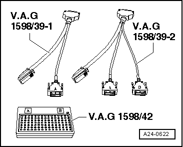
Test box (105) pins -VAG 1598/42-, see equivalent → Anchor
t  Adaptor cable -VAG 1598/39 1-, see equivalent → Anchor
t  Adaptor cable -VAG 1598/39 2-, see equivalent → Anchor
  Note
t  The test box -VAG 1598/42- has 105 sockets. The engine control unit may be connected using 2 different adapter cables.
t  The engine control unit is connected to the vehicle wiring harness via a 60-pin and 94-pin connector.
t  To check the 60-pin connector of the cable harness, the adapter cable -V.A.G 1598/39-1- is connected with the connector -A- to the test box. Components to the 60-pin connector of the wiring harness. → Current flow diagrams, Electrical fault finding and Fitting locations.
t  To check the 94 pin connector of the cable harness, the adapter cable -V.A.G 1598/39-2- is connected with the connector -A- and -B- to the test box. Components to the 94-pin connector of the wiring harness. → Current flow diagrams, Electrical fault finding and Fitting locations.
t  The tester -VAG 1598/42- is designed to be simultaneously connected to the cable harness going to the engine control unit and the unit itself. The advantage of this is that the engine control electronics can operate while the test box is connected (for example when measuring signals while the engine is working).
t  The relevant test procedure will state whether it is necessary to also connect engine control unit to test box.
t  For the connection of measurement equipment (for example voltage tester -V.A.G 1527 B-, hand-held multimeter -V.A.G 1526 A-, etc.) always use the auxiliary measurement set -V.A.G 1594 A-.
In order to separate the engine control unit connectors from the engine, the engine control unit must be separated from the engine → Chapter.
  WARNING
To avoid the destruction of the electronic components, before connecting the measurement cables, the correct measurement range must be selected and the test conditions must be complied with.
  A24-0622
–  Connect the test box -VAG 1598/42- using the adapter cable -V.A.G 1598/39-1- or the adapter cable -V.A.G 1598/39-2- to the wiring harness. Secure the earth clamp of the test box to the negative terminal of the battery. The relevant test procedure will state whether it is necessary to also connect engine control unit to test box.
–  Carry out the verification as described in the corresponding repair process.
–  Once the checks are done, fit the engine control unit → Chapter.
Following the initial connection of the engine control unit, the following operations must be carried out:
–  Query and erase the fault memory → Chapter.
  A24-0622

Direct diesel injection system control unit: repairs > < Cooling system seal: Check