
Leon Mk1
| Overview: fuel tank and fuel filter with components |
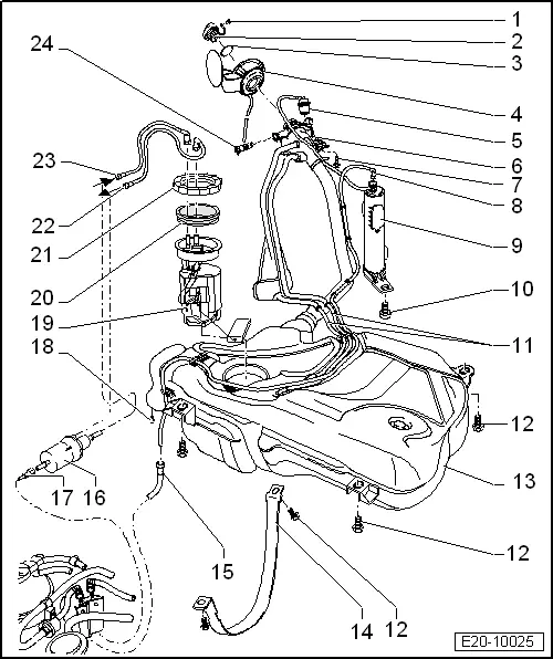
| 1 - | Retaining clip |
| 2 - | Filler cap |
| 3 - | Gasket |
| q | If this is damaged, replace it |
| 4 - | Filler cap set |
| q | With dust guard |
| q | Removing and installing → Bodywork, exterior fitting work; Rep. Gr.55 |
| 5 - | Gravity valve |
| q | For removal, remove the fuel tank cap → Item, undo the securing tab and push the inlet valve out, upwards. |
| q | Check valve continuity |
| t | Perpendicular valve: Open |
| t | Valve inclined 45°: closed. |
| 6 - | Earth connection |
| q | Check that it is seated securely |
| 7 - | Bolt |
| q | 10 Nm |
| 8 - | Breather line |
| q | Between active carbon filter → Item and vent pipe → Item |
| q | Check that it is seated securely |
| 9 - | Active carbon filter |
| q | Installation location: in right rear wheel housing |
| q | Active carbon filter system - Components overview → Chapter |
| 10 - | 10 Nm |
| 11 - | Breather line |
| q | Partly covered by the fuel tank |
| q | Check that it is seated securely |
| 12 - | 25 Nm |
| 13 - | Fuel tank |
| q | removing and installing → Chapter |
| q | If the fuel tank has been replaced, the fuel supply system must be bled → Chapter |
| 14 - | tension belt |
| q | Note the different measurements |
| 15 - | Breather line |
| q | For theSolenoid valve 1 for the active carbon deposit system (pulsed) -N80-, in the engine compartment |
| q | Check that it is seated securely |
| 16 - | Fuel filter: |
| q | Renew → Chapter |
| q | Installation position: The arrow indicates the direction of flow |
| q | The fuel pressure regulator is installed on the fuel filter. |
| q | The fuel system must be bled if the fuel filter has been replaced → Chapter. |
 Note
Note| t | There are pressure controllers that have different control pressures. In this case, the fuel pressure controller with 3 or 4 bars is used. |
| t | When replacing the pressure controller, care must be taken to install the pressure controller type specified by the manufacturer → ETKA (Electronic parts catalogue) |
| 17 - | Fuel supply line |
| q | Black |
| q | To the fuel distributor in the intake manifold |
| q | Check that it is seated securely |
| 18 - | 3 Nm |
| q | For fuel filter securing flange |
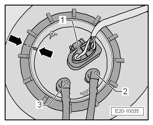
| 19 - | Fuel delivery unit |
| q | removing and installing → Chapter |
| q | Fuel pump and fuel system: checking → Chapter |
| q | Note fitting position on fuel tank → Fig. |
| q | Removing and installing fuel gauge sender -G- → Chapter |
| q | Clean strainer if dirty |
| 20 - | Seal |
| q | If this is damaged, replace it |
| q | Moisten with fuel for installation |
| 21 - | Union nut, 80 Nm |
| q | Remove and install with wrench -3217- . |
| 22 - | Supply pipe |
| q | Black |
| q | Between the fuel pump unit and the fuel filter |
| q | check that it is seated securely |
| 23 - | Return pipe |
| q | Blue colour |
| q | Between the fuel pump unit and the fuel filter |
| q | check that it is seated securely |
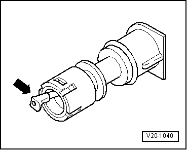
| 24 - | Vent valve |
| q | check → Fig. |
| q | To remove pull locking latch lightly to inside and pull valve out |
Note
|
|