
Leon Mk1
|
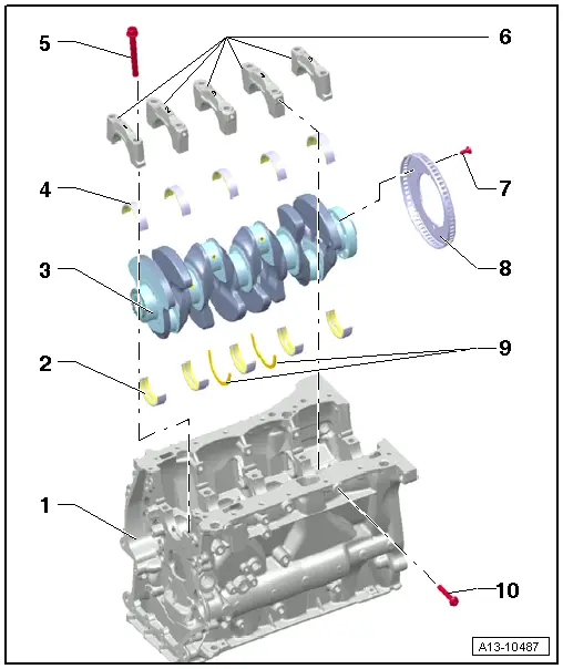
| 1 - | cylinder block |
| 2 - | Engine block bearing shell |
| q | With oil groove |
| q | Do not interchange used bearing shells (mark). |
| q | Identification of the crankshaft bearing shells → Chapter |
| 3 - | Crankshaft |
| q | Following removal, do not place on the impulse generator disk as this will be damaged. |
| q | Axial clearance → Chapter |
| q | Radial clearance → Chapter |
| q | Do not rotate crankshaft when checking radial clearance. |
| q | Crankshaft dimensions → Chapter. |
| 4 - | Bearing cap |
| q | Without oil groove |
| q | Do not interchange used bearing shells (mark). |
| q | The half bearing shells for the bed plate bearing caps are supplied as replacement part only with the colour coding „yellow“ |
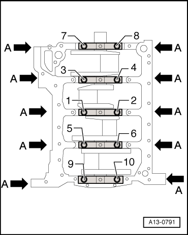
| 5 - | Bolt. |
| q | Replace |
| q | Tightening sequence → Fig. |
| 6 - | Bearing cap |
| q | Bearing cap 1: Pulley side: |
| q | Bearing shell retaining lugs in cylinder block and bearing caps must align. |
| 7 - | Bolt. |
| q | 10 Nm + further 1/4 (90°) |
| q | Replace |
| q | Always renew sender wheel if bolts have been loosened - → Fig. |
| 8 - | Generator wheel: |
| q | For engine speed sender -G28- |
| q | Can only be installed in one position. Holes are off-set |
| q | Always renew sender wheel if bolts have been loosened |
| q | Removing and installing → Fig.. |
| 9 - | Thrust washers |
| q | For bearing 3. |
| 10 - | Bolt. |
| q | 20 Nm + further 1/4 (90°) |
| q | Replace |
 Note
Note
|
|