| –
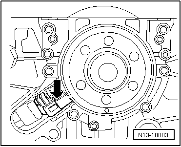
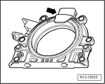
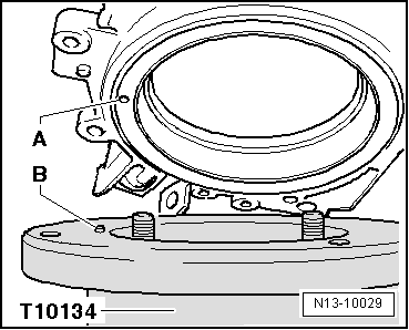
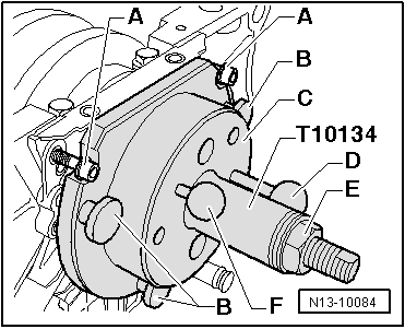
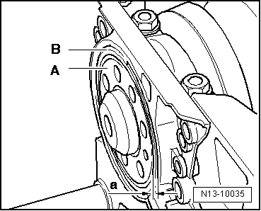
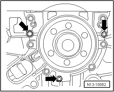
| Screw three bolts M6 x 35 mm into the threaded spaces of the sealing flange -arrows-. |
| –
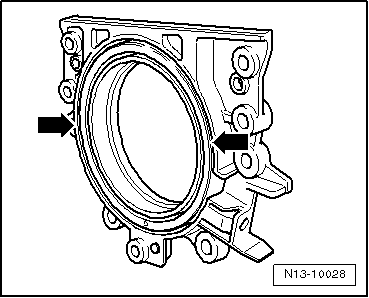
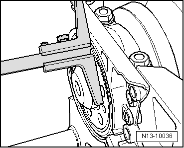
| Alternatively (max.1/2 turn (180°) per bolt), bolts on the sealing flange and remove flange from the crankshaft with the sender wheel. |
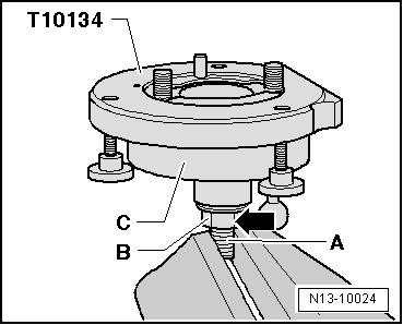
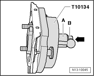
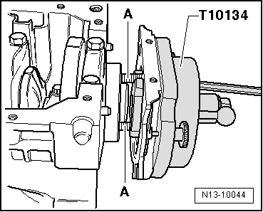
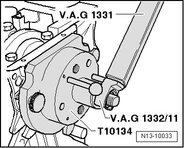
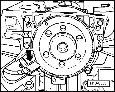
| Drive the sealing flange with sender wheel onto the crankshaft |

Note | t
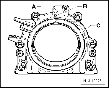
| The sealing flange with the PTFE seal is fitted with a pressure ring on the sealing lip. This support ring acts as an assembly sleeve and must not be removed before installation. |
| t
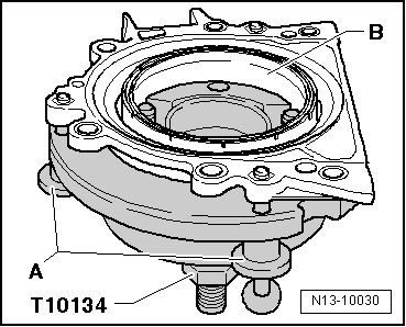
| Sealing flange and sender wheel must not be separated or rotated out of position after removal from packaging. |
| t
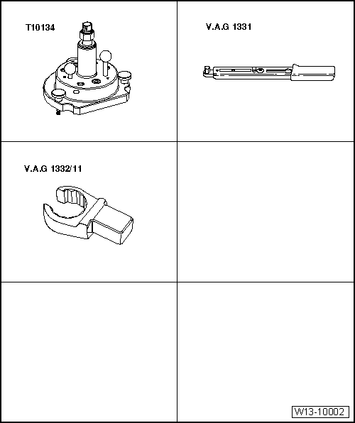
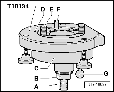
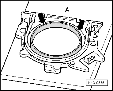
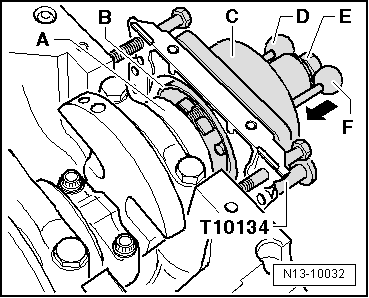
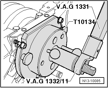
| The sender wheel finds its position automatically when fitted to the position pin of the centre guide -T10134-. |
| t
| Sealing flange and oil seal form one unit and must only be renewed together with the sender wheel. |
| t
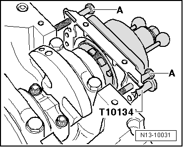
| The position of the centre guide -T10134- with respect to the crankshaft is determined by a guide pin inserted in a borehole in the crankshaft. |
|
|
|