Leon Mk1
| Assembly diagram |
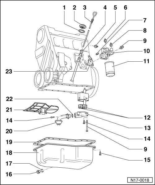
| 1 - | Gasket |
| q | Replace the gasket if there is any damage or deterioration |
| 2 - | Cover |
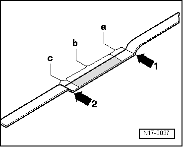
| 3 - | Dipstick |
| q | The oil level must not go above the max. mark! |
| q | Marks → Fig. |
| 4 - | Filling funnel |
| q | Separate for removal of the oil by absorption |
| 5 - | 0.25 bar oil pressure switch -F22-, 25 Nm |
| q | Except for identification letters 1F |
| q | Blue |
| q | Checking → Chapter |
| q | If the sealing ring is leaking, nip open and replace the o-ring |
| 6 - | 1.8 bar oil pressure switch -F1-, 25 Nm |
| q | White |
| q | Checking → Chapter |
| q | If the sealing ring is leaking, nip open and replace the o-ring |
| 7 - | Anti-return valve, 5 Nm |
| 8 - | 0.3 bar oil pressure switch -F22-, 25 Nm |
| q | Brown |
| q | Checking → Chapter |
| q | If the sealing ring is leaking, nip open and replace the o-ring |
| 9 - | 20 Nm |
| 10 - | Oil filter bracket |
| 11 - | Oil filter |
| q | Loosen by the hexagon or using the rotation tool -U-40078- (oil filter spanner) |
| q | Tighten by hand |
| q | Follow the fitting instructions printed on the filter |
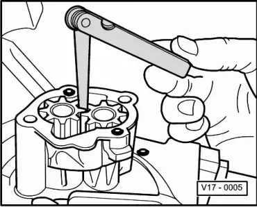
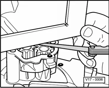
| 12 - | Pinions |
| q | Check the play between gear teeth flanks → Fig. |
| q | Axial play: checking → Fig. |
| 13 - | Oil pump cover with discharge valve |
| q | Opening pressure: 5.7…6.7 bar |
| 14 - | 10 Nm |
| 15 - | 20 Nm |
| q | Loosen and tighten the bolts on the side of the flywheel using the spanner -U-40051A- |
| 16 - | Oil purge bolt, 30 Nm |
| 17 - | Oil seal |
| q | Replacement |
| 18 - | Sump |
| q | Clean sealing surface before installing |
| 19 - | Gasket |
| q | Replacement |
| q | Before fitting, apply -D 454 300 A2- to the contact surface between the sealing flange and engine block |
| 20 - | Suction pipe |
| q | Clean strainer if soiled |
| 21 - | Baffle plate |
| q | To remove this first remove the oil pump cover or the suction tube |
| 22 - | O-ring |
| q | Replace if there is damage or deterioration |
| 23 - | Gasket |
| q | Replacement |
|
|
|
|