seat Workshop Repair Guides

SEAT Workshop Service and Repair Manuals

Engine cooling > < Assembly diagram
Oil pressure and oil pressure switch: verification
   
Oil pressure and oil pressure switch: verification
Special tools and workshop equipment required
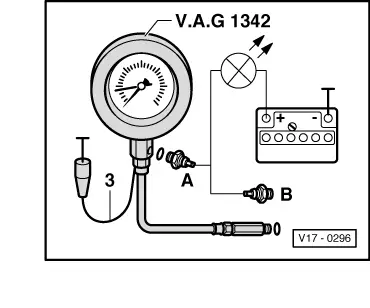
t  Oil pressure tester -V.A.G 1342-
t  Diode test lamp -V.A.G 1527 B-
t  Auxiliary measuring set -V.A.G 1594 A- or -V.A.G 1594 C-

  Note
Functional check and servicing the optical and acoustic oil pressure warning: → Current flow diagrams, Electrical fault finding and Fitting locations.
Checking process
   
–  Remove the 0.3 bar oil pressure switch (brown insulation) and screw the tester into place.
–  Screw tester -V.A.G 1342- into the cylinder head or the oil filter bracket, in place of the oil pressure switch.
–  Connect brown wire of tester to earth (-).
–  Connect diode test lamp -V.A.G 1527 B- using aux. cables from -V.A.G 1594  A- or -V.A.G 1594 C- to battery positive (+) and to the 0.3 bar oil pressure switch -A- (brown insulation). The LED must light up
If the LED does not light up:
–  Replace the oil pressure switch.
LED lights up:
–  Start engine and slowly increase engine revolutions. The LED should turn off between 0.15…0.45 bar; if not replace oil pressure switch.
  V17-0296
–  Connect diode test lamp -V.A.G 1527 B- using aux. cables from -V.A.G 1594 A- or -V.A.G 1594 C- to the 1.8 bar oil pressure switch -B- (white insulation). The LED should turn on between 1.6…2,0 bar of pressure; if not replace oil pressure switch.
–  Increase engine speed further. At 2000 rpm and an oil temperature of 80 °C the oil pressure should be at least 2.0 bar.
At higher engine speed the oil pressure must not exceed 7.0 bar. If necessary, replace the oil pump cover with the relief valve.
  V17-0296

Engine cooling > < Assembly diagram