seat Workshop Repair Guides

SEAT Workshop Service and Repair Manuals

Enginecrankshaft group, pistons > < Rules for cleanliness
Engine: fitting
Engine: fitting
For repairs to the clutch:
t  Vehicles with manual gearbox → 6-speed manual gearbox 0BB; Rep. gr.30.
t  Vehicles with dual clutch gearbox → 6-speed dual clutch gearbox 02E; Rep. gr.30.
Installation is carried out in the reverse sequence; note the following:
  Caution
When doing any repair work, especially in the engine compartment, pay attention to the following due to the cramped conditions:
t  All the various lines (e.g. fuel, hydraulic system, active carbon filter system, coolant, refrigerant, brake fluid and vacuum pipes and hoses) and electrical wiring must be installed in their original positions.
t  To avoid damage to lines/wiring, ensure sufficient clearance to all moving or hot components.
Vehicles with manual gearbox:
–  Check clutch release bearing for wear and renew if necessary.
–  Lightly lubricate clutch release bearing, release bearing guide sleeve and splines on input shaft with grease for clutch plate splines -G 000 100-.
All vehicles (continued):
–  Check whether dowel sleeves for centring the engine/gearbox assembly are fitted in the cylinder block; install if necessary.
   
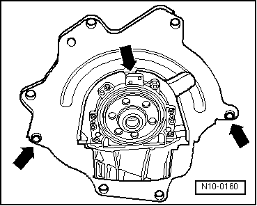
–  Hook intermediate plate onto sealing flange and slide onto dowel sleeves -arrows-.
Vehicles with manual gearbox:
–  Install the line of the clutch slave cylinder with the hydraulic clutch: → 0BB 6-speed manual gearbox; Rep. gr.30
–  Install gearbox shift mechanism and adjust if necessary → 6-speed manual gearbox 0BB; Rep. gr.34.
Vehicles with dual clutch gearbox:
–  Install gearbox selector lever cable and adjust if necessary → 6-speed dual clutch gearbox 02E; Rep. gr.34.
All vehicles (continued):
Align engine mountings as follows:
  N10-0160
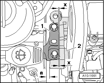
t  There must be a distance -a- of at least 10 mm between engine support and longitudinal member (right side).
t  The side surface of the engine support -2- should be located parallel to the support arm -1-.
  A10-1661
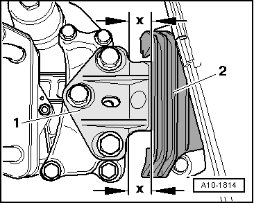
t  Ensure that edges of support arm -1- and gearbox console -2- are parallel.
–  Install the exhaust pipe.
–  Fitting the driveshafts: → Running gear, shafts, steering; Rep. gr.40
–  Install the pendulum support.
  Note
Specified torques for assembly mountings → Chapter.
–  Fitting air conditioning compressor: → Heating, air conditioning; Rep. gr.87.
–  Install poly V-belt → Chapter.
–  Electrical connections and routing → Electrical system; Rep. gr.97
–  Fill up with coolant → Chapter.
–  Install air filter → Chapter.
–  Install battery and battery tray → Electrical system; Rep. gr.27.
–  Connect battery → Electrical system; Rep. gr.27.
  A10-1814
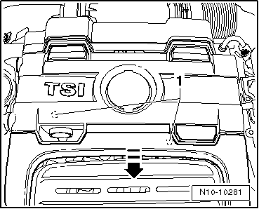
–  Push down engine cover panel at points -1- in direction of -arrow- until engine cover panel engages.
–  Connect Vehicle diagnosis and service information system -VAS 5051B-.
–  Erase learnt values and adapt engine control unit to throttle valve module → Vehicle diagnostic tester„Guided Functions“.
–  Perform vehicle system test → Vehicle diagnostic tester„Guided fault finding“.
–  Finish the vehicle system test so that any fault entries stored during assembly can be erased automatically.
Note safety precautions applicable to a road test.
–  Perform road test.
–  Then carry out vehicle system test again and rectify any faults which have occurred.
  N10-10281

Enginecrankshaft group, pistons > < Rules for cleanliness