seat Workshop Repair Guides

SEAT Workshop Service and Repair Manuals

Intake manifold > < Injectors
Removing and installing high-pressure pump
Special tools and workshop equipment required
   
t  Torque wrench -V.A.G 1410-
  W00-0554
t  Hose clip pliers -VAS 6340-
Removal:
Observe safety precautions → Chapter.
Observe rules for cleanliness → Chapter.
  W00-10380
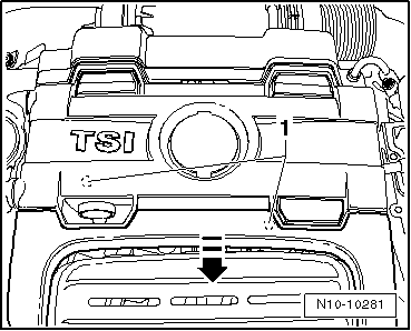
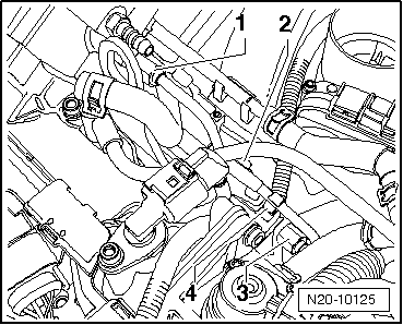
–  Lift off engine cover panel at points -1- and pull it forwards in direction of -arrow-.
  WARNING
The injection system is sub-divided into a high pressure system (max. approx. 120 bar) and a low pressure system (approx. 6 bar).
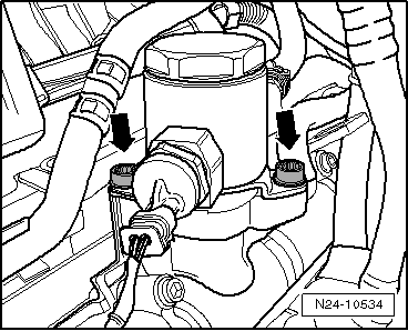
Prior to opening the high-pressure area, e.g. when removing the high-pressure pump, fuel rail, injectors, a fuel line, or the fuel pressure sender -G247-, the fuel pressure in the high-pressure area must be reduced to a residual pressure of approx. 6 bar. The appropriate procedure is described in the chapter on releasing pressure in the high-pressure section → Chapter.
  N10-10281
–  Separate fuel supply line -arrow-.
–  Remove intake connecting pipe → Item.
  N20-10127
–  Pull connector and fuel supply line -arrows- off high-pressure pump.
  Note
Catch escaping fuel in a cloth.
  N15-10479
–  Remove wiring guide -2- and take clip -4- off high-pressure line.
  Note
Use a spanner to counterhold threaded connections on high pressure pump and on lower part of intake manifold when loosening union nuts.
  Caution
Only grasp high-pressure pump on housing when removing and installing!
When the high-pressure piston spring package loosens the high-pressure pump will leak and must be replaced.
–  Loosen union nuts -1- and -3- of high-pressure line.
  N20-10125
–  Evenly unscrew securing bolts -arrows-.
  N24-10534
–  Pull high-pressure pump -3- and roller tappet -1- out of camshaft housing.
Installation
  Caution
Only grasp high-pressure pump on housing when removing and installing!
When the high-pressure piston spring package loosens the high-pressure pump will leak and must be replaced.
Installation is carried out in the reverse sequence; note the following:
  Note
t  Moisten high-pressure pump roller tappet with clean engine oil.
t  The high-pressure pump O-ring must always be renewed.
–  Slide roller tappet -1- into camshaft housing.
  N20-10218
–  Insert new, lubricated O-ring -2- in groove of high-pressure pump -3-.
–  Place high-pressure pump -3- onto camshaft housing.
  N20-10218
–  Screw in securing bolts -arrows- by hand until bolt heads are seated on flange.
–  Tighten securing bolts -arrows- evenly until flange is seated on camshaft housing.
Tightening torque: 20 Nm
  N24-10534
–  Tighten union nuts of high-pressure line -1- and -3- hand-tight.
–  Install wiring guide -2- and fit clip -4- on high-pressure line.
Tightening torque of the fixing bolts of the guide: 8 Nm
  Note
Use a spanner to counterhold threaded connections on high-pressure pump and on lower part of intake manifold when tightening union nuts.
  N20-10125
–  Tighten union nut -1- of high-pressure line to 18 Nm.
–  Tighten union nut -3- of high-pressure line to 18 Nm.
  N20-10125
–  Secure fuel supply line and connector -arrows- on high-pressure pump.
  N15-10479
–  Reconnect fuel supply line -arrow-.
–  Install intake connecting pipe and air filter → Chapter.
  N20-10127

Intake manifold > < Injectors