seat Workshop Repair Guides

SEAT Workshop Service and Repair Manuals

Checking compression > < Removing and installing camshaft housing|Installation
Removing and installing cylinder head
   
Removing and installing cylinder head
Special tools and workshop equipment required
t  Support bracket -10 - 222 A-
t  Rack -10 - 222 A /1-
t  Spring retainer -T10358-
t  Torque wrench (40…200 Nm) -V.A.G 1332-
t  Torque wrench (5…50 Nm) -V.A.G 1331-

   
t  Adapters -10 - 222 A /28-
t  To avoid damaging wing edges, apply adhesive tape -arrow- to bottom areas of both adapters -10 - 222 A /28-.
  N34-11564
Removal:
–  Unplug connector -1-.
–  Remove bolts -arrows-.
l  Gas hoses remain connected to gas rail.
–  Release the wiring from the fixing of the carrier cover and from the gas hoses.
–  Place the fuel rail „Gas rail“ aside and fix without removing the cables and hoses.
  E00-10900
–  Remove bolts -arrows- and lift the carrier cover upwards and away.
–  Remove the air filter housing → Chapter.
–  Remove expanded plastic components or seals in area of wing edges.
  E00-10901
–  Remove plenum chamber cover -1- in exterior area → Body - front; Rep. gr.50.
–  Place support bracket -10 - 222 A- with adapter -10 - 222 A /8- behind bonnet stay.

–  Place adapter -10 - 222 A /8- behind bend -2-.
  Note
Plenum chamber cover is in contact with adapters -10 - 222 A /8-.
–  Hook support bracket -10-222 A- into right suspension eye only.
–  Remove air duct from air filter with spring-type clip pliers -VAS 5024A- → Chapter.
   
–  Unscrew securing bolt for gearbox and bolt bracket -T10358- on as shown.
–  Attach hooks of support bracket -10 - 222 A- to bracket -T10358- as shown.
–  Turn spindles until the hooks are lightly tensioned.
  N15-10347
–  Unhook hook -1- from left lifting eye and push spindle onto left side of support bracket -10 - 222 A-.
Remove the following components:
t  Drain coolant → Chapter.
t  Remove intake manifold → Chapter.
t  Remove valve timing housing → Chapter.
t  Remove timing chain and drive chain for oil pump → Chapter.
t  Remove thermostat housing from cylinder head.
t  Remove the exhaust manifold with precatalyst.
–  Remove camshaft housing → Chapter.
–  Remove roller rocker fingers together with support elements and lay aside on clean surface.
–  Ensure the roller rocker fingers and the support elements are not confused.
  N15-10348
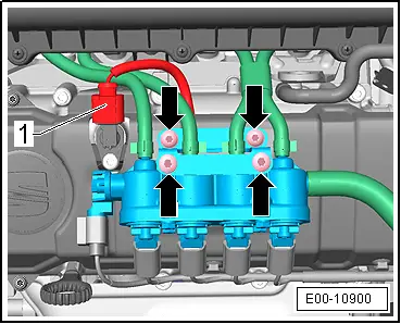
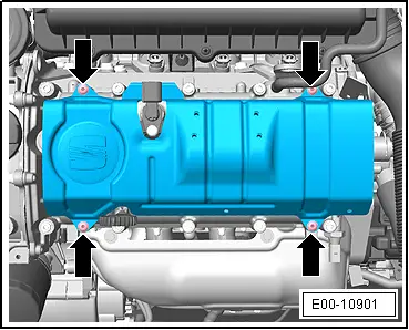
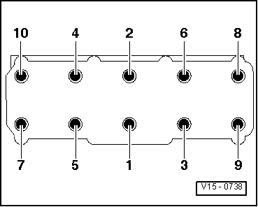
–  Loosen socket head bolts in the sequence given and then remove completely.
–  Carefully remove cylinder head.
Installation
Requirements:
l  Pistons must not be at TDC.
  Note
t  Do not remove the new cylinder head gasket from its packing until immediately before its installation.
t  Handle new gasket with extreme care. If damaged, leaks may result.
–  Place clean cloths in cylinders so that no dirt or emery cloth particles can get in between cylinder wall and piston.
–  Carefully clean the sealing surfaces on the cylinder head and cylinder block. Ensure no long grooves or scratches are produced (if using sandpaper. it must be at least 100 grain).
–  Carefully remove metal particles, emery residue and cloths.
–  Set No. 1 cylinder piston to top dead centre and then turn crankshaft back slightly.
–  Fit new cylinder head gasket. Lettering (Part No.) must be readable.
–  Fit cylinder head. When doing this, observe centring pins in cylinder block.
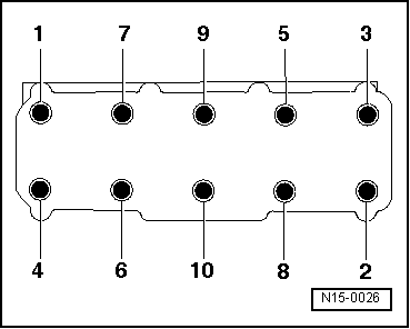
–  Insert cylinder head bolts and tighten by hand.
  N15-0026
–  Tighten cylinder head bolts in tightening sequence as follows:
–  Tighten all bolts to 30 Nm.
–  Then tighten all bolts 1/4 turn (90°) further using a rigid wrench.
–  Then tighten all bolts again 1/4 turn (90°) further
–  Install supporting elements in cylinder head and fit respective roller rocker finger onto respective valve stem end or supporting element.
–  Fit camshaft housing → Chapter
–  Install timing chain and drive chain of oil pump → Chapter.
–  Adjust distribution timing → Chapter.
–  Fit distribution casing → Chapter.
Further assembly is basically the reverse of the dismantling sequence.
  V15-0738
–  Install the carrier cover and tighten the screws -arrows- to a tightening torque of 8.5 Nm.
–  Mount the cables and gas hoses on to the fixing points of the carrier cover.
  E00-10901
–  Install the fuel rail „Gas rail“ and tighten the screws -arrows- to a tightening torque of 4 ± 0.4 Nm.
–  Insert the connector -1-.
  E00-10900

Checking compression > < Removing and installing camshaft housing|Installation