seat Workshop Repair Guides

SEAT Workshop Service and Repair Manuals

Engine cooling > < Oil filter, engine oil cooler and oil pressure switch
Removing and installing sump (top section)
   
Removing and installing sump (top section)
Special tools and workshop equipment required
t  attachment tool -T10118-
t  Brake pad wear tester -VW 136-
t  Torque wrench -V.A.G 1331-
t  Silicone sealant -D 174 003 A2-

Removing:
–  Remove gearbox → Rep. gr.34.
–  Remove oil pump → Chapter.
–  Remove sealing flange (gearbox end) → Chapter.
–  Remove right wheel housing liner → Bodywork, exterior fitting work; Rep. gr.66.
   
–  Remove bolts -arrows-.
–  Remove the air conduit tube, lifting the clips -1 and 2- for this purpose.
  A21-10162
–  Remove bolt -1-.
–  Unscrew the line bracket on the upper element of the oil sump next to the coolant circulation pump -V51-.
  A21-10161
–  Remove bolts -arrows-.
  DANGER!
Injury risk! The chain tensioner spring for oil pump drive jumps from sump (top section) to timing chain cover (bottom) when detaching sump (top section). Do not reach between sump (top section) and timing chain cover (bottom) when removing sump (top section).
  N17-10200
–  Remove bolts -1 to 14- and lever off upper part of sump.
  Caution
First remove the upper element of the oil sump on the gearbox side. Lift carefully so that the cover and the chain do not deform.
Installing:
l  Tightening torque → Chapter
  Note
t  Note the expiry date of the silicone sealant.
t  The sump (top section) must be installed within 5 minutes after applying the silicone sealant.
  A17-10273
–  Fit the assembly tool -T10118- and pull the spring of the chain tensioner for the oil pump drive in the direction of the -arrow-.
–  Secure the spring. For this purpose, insert the testing equipment for brake pad wear -VW 136- into the borehole of the guide shoe as shown in the figure.
–  Remove sealant residue from cylinder block using a flat scraper.
  WARNING
Protect eyes against injuries.
Wear safety goggles.
  N17-10163
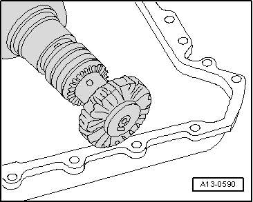
–  Remove remaining sealant on upper part of the oil sump and lower timing chain cover e.g. using rotating plastic brush.
  Note
Check timing chain cover for deformation. To do this, fit sump upper part first without sealant and check gap between cover and sump upper part. If deformation is evident and cover cannot be aligned, renew cover after upper part of sump has been installed.
–  Clean sealing surfaces; they must be free of oil and grease.
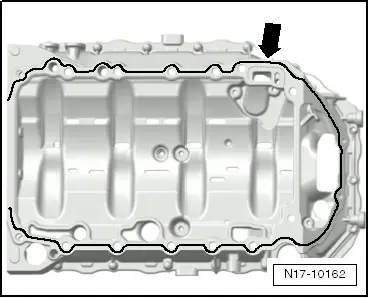
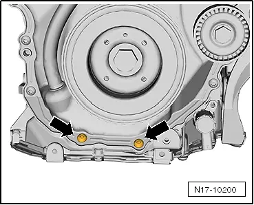
–  Check oil passages in sump (top section) and crankcase for contamination.
  A13-0590
–  Cut off tube nozzle at upper marking (nozzle Ø: approx. 3 mm).
  A17-0081
–  Apply silicone sealant -D 174 003 A2- onto clean sealing surface of upper part of sump, as illustrated -arrow-.
l  Thickness of the sealant grub: 2 ... 3 mm
  Note
t  The sump (top section) must be installed within 5 minutes after applying the silicone sealant.
t  The bead of sealant must not be thicker than specified, otherwise excess sealant can enter the sump and obstruct the strainer in the oil intake pipe.
l  The upper element of the oil sump and the crankshaft sump must connect flush on the gearbox side.
  N17-10162
–  Then position the upper element of the oil sump and then tighten the screws -1 to 14- in three stages as follows:
1 - Tighten bolts by hand
2 - When tightening bolts, apply 15 Nm torque
3 - Turn bolts 90° further.
  A17-10273
–  Fit bolts -arrows-. Tightening torque → Fig.
  N17-10200
–  Remove the testing equipment for brake pad wear -VW 136- from the guide shoe -arrow-. The spring returns to its initial position.
Further assembly is basically the reverse of the dismantling sequence.
  N17-10201

Engine cooling > < Oil filter, engine oil cooler and oil pressure switch