seat Workshop Repair Guides

SEAT Workshop Service and Repair Manuals

Diesel direct injection system: repair > < Engine control unit: replace, code and adapt
Speed signal: check
Speed signal: check
Special tools and workshop equipment required
t  Fault reader -V.A.G 1551- or vehicle system checker -V.A.G 1552- with cable -V.A.G 1551/3B-
t  
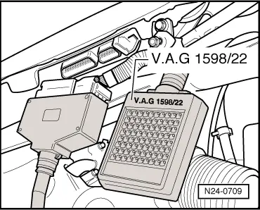
Checking box -V.A.G 1598/22-
t  Manual multimeter -V.A.G 1526 A- or multimeter -V.A.G 1715-
t  Auxiliary measuring set -V.A.G 1594 C-
t  Current circuit diagrams
Checking conditions
l  Speedometer correct, check → Electrical system; Rep. Gr.90
l  Battery voltage, 11.5 V minimum.
l  All electrical consumers, for example: the lights and heated windscreen, must be turned off.
Checking process
  Note!
To check the speed signal, the vehicle must be driven. To do this, the help of a second person is required.
  Caution
The fault reader must be fixed on the back seat and handled from there.
–  Connect the -V.A.G 1551- (-V.A.G 1552-), and using the corresponding “direction code” 01, select the control unit for engine electronics. When doing this, the engine must be idling: (Fault reader: Turn on and select the control unit for engine electronics → Chapter).
   
Indication on the display:
–  Press the keys 0 and 8 for the function “Read measurement value block” and confirm with Q.
 
Fast data transmission              HELP
Select the function XX                  
Indication on the display:
–  Press the keys 0, 0 and 6 for “Indication group number 6” and confirm with Q.
–  Carry out a test run, noting the indication on the display (the help of another person is required).
Note the necessary precautions when making a test run → Chapter.
 
Read measurement value block            
Enter value group number XXX            
Observe the indication in field 1:
Theoretical value: approx. driving speed
–  Press .
–  Press the keys 0 aund 6 for the function “End data transmission” and confirm with Q.
–  Turn off the ignition.
If no speed is indicated:
 
Read measurement value block 6        ->
0 Kph     0 0 0         000000       255
–  Connect the -V.A.G 1598/22- checking box to the cable harness of the control unit.
–  Turn on the multimeter in voltage measurement between the females: 1+51 and 27+51 of the checking box.
–  Turn on the ignition.
–  Raise the front left part of the vehicle.
–  Turn the front wheel, noting the voltage values that appear. Theoretical value: oscilating between 0 and at least 4 volts
  Note!
On doing this, the front right wheel must not turn, if necessary, fix.
If the value shown does not change:
–  Check for breakage in the cable between the checking box female 51 and the instrument panel, following the current circuit diagram → Current flow diagrams, Electrical fault finding and Fitting locations.
   Cable resistance: 1,5 Ω max.
  N24-0709

Diesel direct injection system: repair > < Engine control unit: replace, code and adapt