
Leon Mk1
| Inlet air temperature sender: verification |
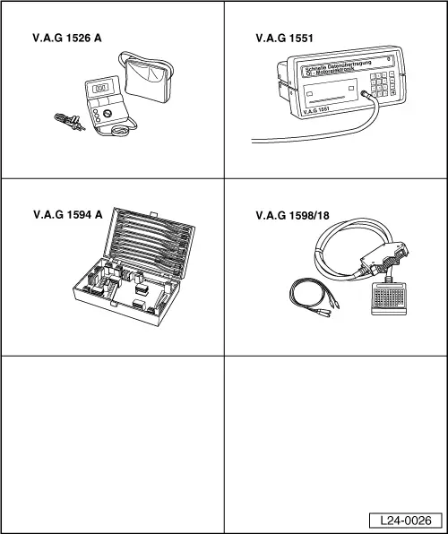
| Special tools and workshop equipment required |
| t | Hand multimeter -V.A.G 1526 A- or multimeter -V.A.G 1715- |
| t | Fault reader -V.A.G 1551- or vehicle system tester -V.A.G 1552- with cable -V.A.G 1551/3B- |
| t | Auxiliary measuring set -V.A.G 1594 C- |
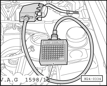
| t | Test box -V.A.G 1598/18- |
| t | Electric circuits flow diagram |
| t | Chilling spray (commercially available) |
|
|
|
|
|
|
|
| Indication | Cause | Continuation of check |
| Approx. -55 °C | Open circuit or short to positive | → Anchor |
| Approx. 130 °C or more | Short circuit to earth | → Anchor |
| Approx. Ambient temperature → Note | — | → Anchor |
| 1) | If the indicated temperature varies significantly from the ambient temperature of the sender, first check the resistance values of the sender cables. |
|
|
|
|
|
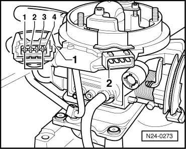
| Pin | Test box -V.A.G 1598/18-, test box socket | |
| 4 | 43 | |
| Cable resistance: 1.5 Ω max. | ||
|
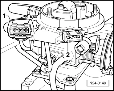
| Pin | Test box -V.A.G 1598/18-, test box socket | |
| 1 | 17 | |
| Cable resistance: 1.5 Ω max. | ||
|
|
|
|
|