seat Workshop Repair Guides

SEAT Workshop Service and Repair Manuals

Components and functions: verification > < Velocity signal: verification
Air conditioning signals, two ways: verification
Using the signals from the air conditioning, the compressor from the air conditioning system, when it is switched on, rises to the previous control level for idle stabilization. In this way, the idle stabilisation remains in the centre of the regulation range.
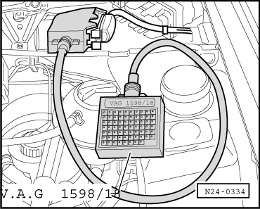
Special tools and workshop equipment required
   
t  Hand multimeter -V.A.G 1526 A- or multimeter -V.A.G 1715-
t  Fault reader -V.A.G 1551- or vehicle system tester -V.A.G 1552- with cable -V.A.G 1551/3B-
t  Auxiliary measuring set -V.A.G 1594 C-
  W00-0431
t  Test box -V.A.G 1598/18-
t  Electric circuits flow diagram
Test conditions
l  Air conditioning operation, correct.
l  The air conditioning must be OFF
l  There should be no recorded faults already in the memory → Chapter, Fault memory: consulting.
l  The vehicle should be at ambient temperature (more than +15 °C).
Checking process
–  Connect the equipment -V.A.G 1551- (-V.A.G 1552-). Start engine and select “Address code” 01 to select engine control unit. (Fault reader: Connecting and selecting the engine control unit → Chapter.)
  W00-0478
Display indication:
–  Press the keys 0 and 8 for the function “Read measurement block values”, confirm using the key Q.
 
Rapid data transmission             HELP
Select the function XX                  
Display indication:
–  Press keys 0, 0 and 1 for “Display group number 1” and confirm entry with Q key.
 
Read measurement block values       HELP
Input the indication group number XX    
Display indication:
(1…4 = Display fields)
–  Note the 8 digit numerical block in the indication field 4. The 4th and 5th digit from the right should read 0.
   Indication: 01000000
–  Connect the air conditioning. Put the minimum temperature and the maximum turbine speed.
   The 4th and 5th digits from the right should be 1.
   Indication: 01011111
   4th digit from the right = air conditioning ON
   5th digit from the right = air conditioning compressor ON
If the described indication does not appear:
 
Read measurement value block         1->
         1         2         3         4
–  Connect the tester -V.A.G 1598/18- to the control unit cable harness.
–  Check the cables between the test box sockets 33 and 35 and the air-conditioning for open circuit or interruption, according to the electric current circuits diagram.
   Cable resistance: 1.5 Ω max.
  N24-0334

Components and functions: verification > < Velocity signal: verification