seat Workshop Repair Guides

SEAT Workshop Service and Repair Manuals

Gearbox: Removing and installing > < Clutch and lock plate: Removing and installing
Electric/electronic components and assembly positions
   
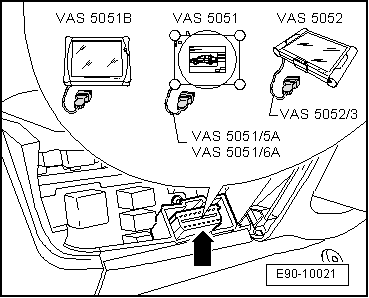
Location of diagnostic connector
The diagnosis connector is located below the footwell cover, driver's side → Bodywork, interior fitting work; Rep. Gr.68.
  E90-10021
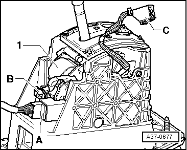
Magnet for selector lever locking -N110-
The selection lever locking magnet -N110--1- is located on the gearbox operation mechanism.
The magnet is a fixed component of the gear selection mechanism, and can therefore not be replaced separately. It can only be removed or fitted together with the gear selection mechanism → Chapter.
  A37-0677
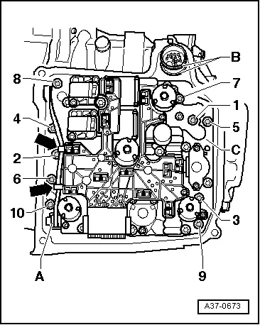
DSG automatic gear mecatronic system -J743-
the mecatronic unit for the DSG automatic gearbox -J743- is bolted onto the front part of the gearbox and is covered by the gear oil sump.
The control unit is integrated into the mecatronic unit for the DSG automatic gearbox -J743-.
t  Verified by self-diagnosis
Remove and fit the DSG automatic gear mecatronic system -J743- → Chapter
  A37-0673
Tiptronic switch -F189-
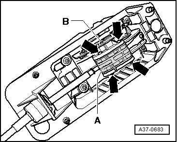
The Tiptronic switch -F189- is an integral component of the printed circuit board -B- of the gear selection mechanism.
t  Verified by self-diagnosis
The Tiptronic switch -F189- is a fixed component of the gear selection mechanism, and can therefore not be replaced separately. It can only be removed or fitted together with the gear selection mechanism → Chapter.
  A37-0683
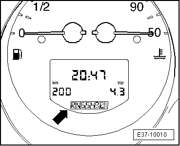
Gear selector position indicator -Y6-
Fitting location: integrated on the instrument panel
  Note
The selector lever position indicator can only be replaced together with the dash panel.
If the selector lever position indicator is flashing or lit up, the gearbox control unit safety functions should be observed → Chapter.
t  Removing and assembling the selector lever position indicator -Y6- → Electrical system; Rep. Gr.90
  E37-10010
Selector level locking switch in P -F319-
Location: the selector level locking switch in P -F319- is an integral component of the printed circuit board -B- of the gear selection control.
t  Verified by self-diagnosis
It is necessary to replace the gear selection mechanism in order to change the switch → Chapter.
  A37-0683
Selector lever -E313-
Location: the electrical component selector lever -E313- is an integral component of the printed circuit board -B- of the gear selection control.
t  Verified by self-diagnosis
It is necessary to replace the gear selection mechanism in order to change the switch → Chapter.
  A37-0683
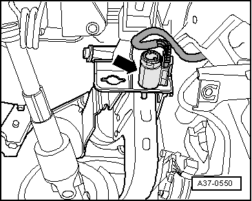
Brake light switch -F-
Fitting location: the brake light switch -arrow- is located in the pedal area.
t  Verified by self-diagnosis
t  Removing and fitting → brake system; Rep. Gr.46.
  Note
To ensure a good fit, the switch should only be mounted once.
  A37-0550
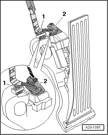
Kick-down switch -F8-
Fitting location:
t  In vehicles with a petrol-fuelled engine a set value is stored by the accelerator pedal position senders -G79/G185-, in the engine control unit.
t  Verified by self-diagnosis
t  Signal transmission from the engine control unit to the gearbox control unit is through the CAN bus
t  Removing and installing accelerator pedal module → Fuel supply, petrol engines; Rep. Gr.20
  A20-1087

Gearbox: Removing and installing > < Clutch and lock plate: Removing and installing