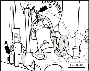
| Suspension strut to suspension strut dome | 15 Nm + 90° |
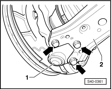
Wheel-bearing housing to suspension strut| t
| Use new screws and nuts! |
| 60 Nm + 90° |
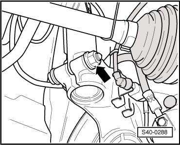
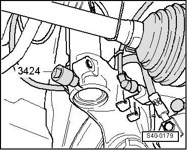
| Track rod end/track rod to steering arm | 20 Nm + 90° |
| The anti-roll bar on the suspension strut | 40 Nm |
Twelve-point nut for securing the drive shaft to wheel hub with mechanical steering| t
| Do not grease thread of the outer joint of the drive shaft. |
| 50 Nm |
Twelve-point nut for securing the drive shaft to wheel hub with power-assisted steering| t
| Do not grease thread of the outer joint of the drive shaft. |
| 50 Nm + 45° |
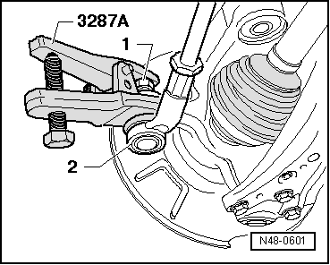
| Steering joint to track control arm | 20 Nm + 90° |
| Wheel bolts | 120 Nm |

 Note
Note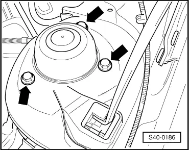
 Caution