
Fabia Mk1
|
|
| Maximum dimensions in mm | 1.0 ltr. engine | 1.4 ltr. engine |
| Inlet valve | 43,1 | 42,7 |
| Exhaust valve | 43,0 | 42,8 |
|
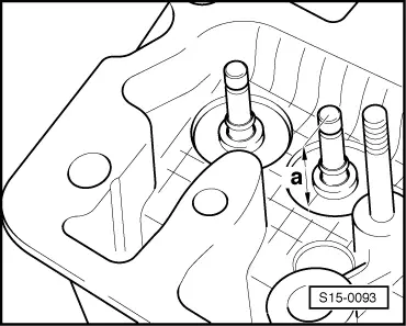
| Maximum dimension | 43,1 | mm | |
| - | Measured distance | 42,7 | mm |
| = | max. permissible reworking dimension | 0,4 | mm |
 Note
Note
|
|
|
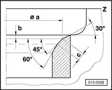
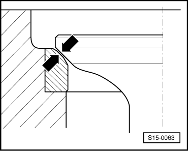
| Dimension | Valve seats | ||
| 1.0 ltr. engine: | |||
| Ø a | mm | Valve seat diameter: | 33,4 ± 0.1 - inlet valve 26.4 ± 0.1 - exhaust valve |
| 1.4 ltr. engine: | |||
| Ø a | mm | Valve seat diameter: | 32.9 -0.1 - inlet valve 29.6 -0.1 - exhaust valve |
| b | mm | max. permissible reworking dimension | |
| 1.0 ltr. engine: | |||
| c | mm | Valve seat width: | 1.3 up to 1.6 - inlet and exhaust valve |
| 1.4 ltr. engine: | |||
| c | mm | Valve seat width: | 1,45 up to 1,75 - inlet valve 1,65 up to 1,95 - exhaust valve |
| Z | Bottom edge of cylinder head | ||
| 45° | Valve seat angle | ||
| 30° | Top correction angle | ||
| 60° | Bottom correction angle | ||
|
|
|
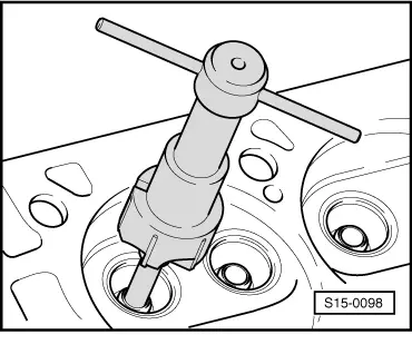
| Valve guide | Ø Guide drift in mm |
| Inlet valve | 7,0 -0,01 |
| Exhaust valve |
|
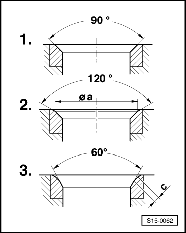
| Valve seat | Ø Milling cutter 90 mm | Ø Milling cutter 120 mm | Ø Milling cutter 60 mm | |
| Inlet valve | 1.0 ltr. engine | 36 | 38 | 21/34 |
| 1.4 ltr. engine | 36 | 38 | 21/34 | |
| Exhaust valve | 1.0 ltr. engine | 30 | 30 | max. 30 → Note |
| 1.4 ltr. engine | 32 | 32 | 21/34 | |
|
|
|
Note
|
|