
Fabia Mk1
 Note
Note| t | Before installing heat the inner ring of the tapered-roller bearing to 100°C. |
| t | Replace both tapered-roller bearings together. |
| t | When replacing the tapered-roller bearing of the differential housing, gearbox housing and clutch housing adjust the differential → Chapter. |
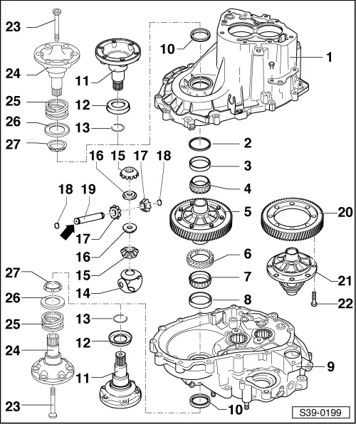
| 1 - | Gearbox housing |
| 2 - | Adjusting washer |
| q | for the differential gear |
| q | Determine thickness → Chapter |
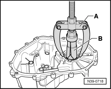
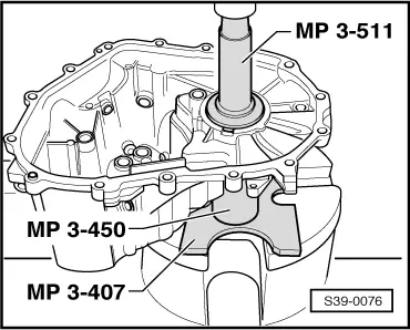
| 3 - | Outer ring/tapered-roller bearing |
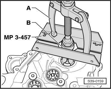
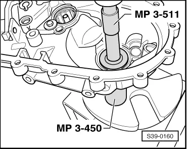
| q | removing → Fig. |
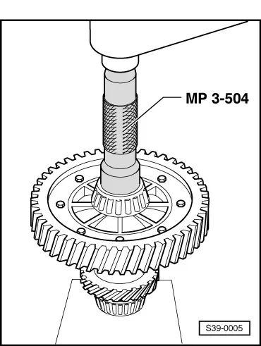
| q | pressing on → Fig. |
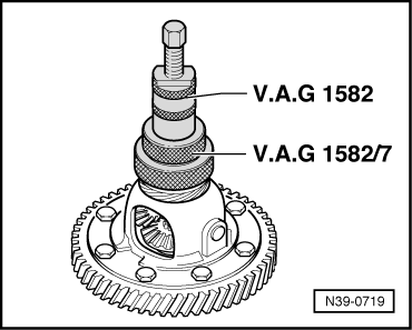
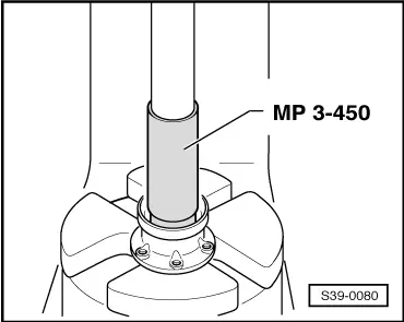
| 4 - | Inner ring/tapered-roller bearing |
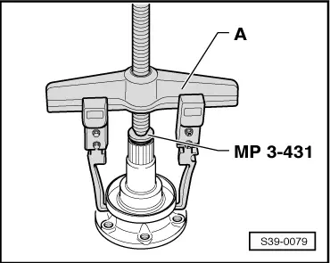
| q | remove → Fig. |
| q | pressing on → Fig. |
| 5 - | Differential gear housing with pinion |
| 6 - | Drive wheel for speedometer |
| q | only for vehicles without ABS; from 11.02 |
| q | before pressing on the inner ring place it on the differential gear housing up to the stop |
| 7 - | Inner ring/tapered-roller bearing |
| q | remove → Fig. |
| q | pressing on → Fig. |
| 8 - | Outer ring/tapered-roller bearing |
| q | removing → Fig. |
| q | pressing on → Fig. |
| 9 - | Clutch housing |
| 10 - | Gasket ring |
| q | replace → Chapter |
| 11 - | Flange shaft |
| q | for gearbox up to 06.00 |
| q | removing and installing → Chapter |
| 12 - | Dust cap |
| q | for gearbox up to 06.00 |
| q | for flange shaft |
| q | remove → Fig. |
| q | pressing on → Fig. |
| 13 - | Circlip |
| q | for gearbox up to 06.00 |
| q | always replace |
| 14 - | Stop disc compound |
| q | when installing moisten with gearbox oil |
| 15 - | Differential bevel gear large |
| q | pay attention to different versions |
| q | Installation for gearbox up to 06.00 → Fig. |
| q | Installation for gearbox after 06/00 → Fig. |
| 16 - | Threaded part |
| q | for gearbox after 06.00 |
| q | installing → Fig. |
| 17 - | Differential bevel gear small |
| q | Installation for gearbox up to 06.00 → Fig. |
| q | Installation for gearbox after 06/00 → Fig. |
| 18 - | Circlip |
| q | always replace |
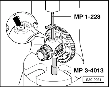
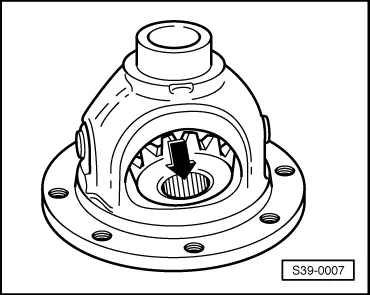
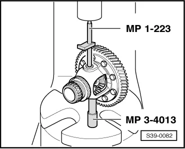
| 19 - | Differential bevel gear shaft |
| q | Shaft has a different diameter, front side with centering hole -arrow- means a smaller diameter |
| q | pressing out → Fig. |
| q | pressing on → Fig. |
| 20 - | Pinion for final drive |
| q | is paired with the output shaft, replace together |
| 21 - | Differential housing |
| q | screw to pinion for final drive |
| 22 - | 80 Nm |
| q | before tightening apply locking agent (e.g. -THREE BOND 1375 B-) |
| 23 - | Conical screw, 25 Nm |
| q | for gearbox after 06.00 |
| q | screw into threaded piece |
| 24 - | Flange shaft |
| q | for gearbox after 06.00 |
| 25 - | Pressure spring for flange shaft |
| q | for gearbox after 06.00 |
| q | fitted behind flange shaft |
| 26 - | Thrust washer |
| q | for gearbox after 06.00 |
| q | Fitting position: Collar towards pressure spring |
| 27 - | Conical ring |
| q | for gearbox after 06.00 |
| q | Fitting position: Cone towards differential housing |
|
|
|
|
Note
|
|
Note
|
|
|
|
Note
|
|
|
|
|
|
|
|
|
|
|
|
|
|