skoda Workshop Repair Guides

Skoda Workshop Service and Repair Manuals

Removing and installing the cylinder head|Install > < Removing and installing the cylinder head
Removing
Removing
Requirements
l  Engine temperature should not exceed 35 °C, because the cylinder head could be twisted when slackening the screws.
l  The pistons must not be in TDC.
–  Switch off ignition and withdraw ignition key.
   
–  Remove noise insulation -arrows-.
–  Remove pre-exhaust pipe with catalytic converter → Chapter.
–  Drain coolant → Chapter.
  S10-0114
–  Remove engine cover.
   Pull the front and rear engine cover upwards with a sudden motion -arrows-.
–  Remove injection lines.
  Note
To do so, use a special ring spanner for injection lines.
–  Remove the return-flow lines from the injection nozzles and the injection pump.
–  Separate the plug connection of the needle stroke sender cable and remove plug from holder.
–  Disconnect glow plug edge connector.
  S10-0115
–  Disconnect plug connection for intake manifold flap -1-.
–  Remove intake hose -2-.
–  Remove pressure control valve -3- with connected ventilation tube.
–  Unscrew bolts -4-.
–  Detach coolant hose -5- and top coolant pipe -5-.
–  Disconnect vacuum hose -6- from the mechanical exhaust gas recirculation valve.
  S15-0152
–  Unscrew support for coolant line -2- with the hoses connected -arrows-.
–  Disconnect the coolant hose -1- from the cylinder head at the connection fitting.
–  Unscrew both top screws of rear toothed belt guard.
–  Remove top part of rear toothed belt guard.
–  Remove cylinder head cover and oil deflector.
–  Remove vacuum pump.
  S15-0153
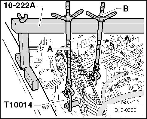
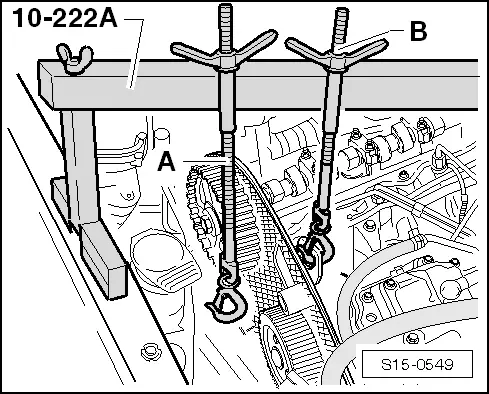
–  Install supporting device -MP9-200 (10-222 A)- and support the engine with screw -B- in fitting position as shown.
  Note
Both lifting eyes are located on the cylinder head, this is why an additional holder must be fitted on the cylinder block to support the engine.
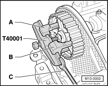
–  Turn crankshaft on TDC for cylinder 1, lock injection pump gear (screw the pump gear loosely to the hub with new screws), remove engine mounting and engine support → Chapter.
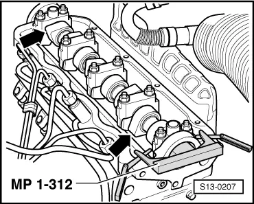
–  Remove toothed belt from the camshaft timing gear and injection pump gear.
  Note
t  The vibration damper and the middle and bottom toothed belt guards can remain installed.
t  The timing belt remains fitted onto the crankshaft timing belt sprocket.
–  Turn crankshaft slightly back.
  S15-0549
–  Lock the camshaft with the camshaft straightedge -MP1-312-.
  Note
The valves for cylinder 1 must be closed and the valves for cylinder 4 must overlap.
–  Centre camshaft straightedge as follows:
   Turn locked camshaft in such a way that one end of the camshaft straightedge strikes the cylinder head. Measure the resulting gap at the other end of the camshaft straightedge with a feeler gauge.
Insert feeler gauge with halved thickness between the camshaft straightedge and the cylinder head. Turn the camshaft until one end of the camshaft straightedge strikes the feeler gauge.
Insert the second feeler gauge of the same thickness between the opposite end of the straightedge and the cylinder head.
–  Loosen the fixing bolt of the camshaft timing gear by one turn. While doing so counterhold the camshaft timing gear with counterholder -T30004- or -MP1-216-.
  S13-0207
–  Position extractor -T40001- with single-arm claw-A- and two-arm claw-B- in the centre of the camshaft timing gear and detach the camshaft timing gear.
   To do so, counterhold the extractor with the assembly spanner -C-.
  M13-0002
–  Screw the bracket -T10014- into the front bore after removing the engine support in the top part of the coolant pump at the cylinder block.
–  Raise the engine slightly with the second screw-A- until the screw-B- is relieved.
–  Push screw-B- aside.
–  Remove tensioning pulley.
  S15-0550
–  Slacken cylinder head bolts in the specified order and unscrew.
–  Carefully remove the cylinder head, while doing so carefully guide the pin screw out of the timing belt guard.
  N15-0026

Removing and installing the cylinder head|Install > < Removing and installing the cylinder head