skoda Workshop Repair Guides

Skoda Fabia Workshop Service and Repair Manuals

Install gearbox (Fabia II, Roomster, Rapid) > < Removing and installing the gearbox
Remove gearbox (Fabia II, Roomster, Rapid)
Special tools and workshop equipment required
t  
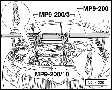
Supporting device -MP9-200 (10-222A)-
t  Cap -MP9-200/3 (10-222A/3)-
t  Hook for MP9-200 and T30099 -MP9-200/10 (10-222A/10)-
t  Engine/gearbox jack -V.A.G 1383 A-
t  Gearbox mount -3282-
t  
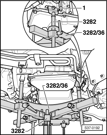
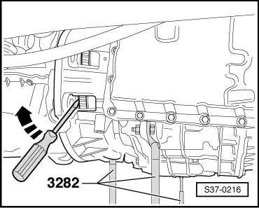
Adjusting plate -3282/36-
t  Wedge -T10161-
t  
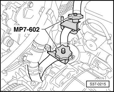
Hose clamps -MP7-602 (3094)-
–  Remove engine cover at the top.
  Note
t  If the battery earth strap is disconnected and connected, carry out additional operations → Electrical System; Rep. gr.27.
t  All cable straps which are detached or cut open when removing, should be fitted on again in the same place when installing.
–  Disconnect the battery-earth strap with the ignition off → Electrical System; Rep. gr.27.
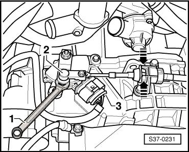
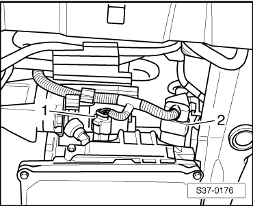
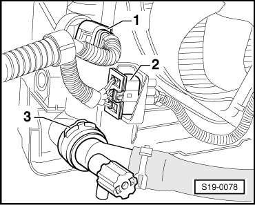
–  Disconnect plug from automatic gearbox control unit -J217-.
–  Remove battery and battery tray → Electrical System; Rep. gr.27.
–  Remove intake hose → Engine; Rep. gr.24.
–  Shift selector lever into position „P“.
   
–  Lever off the selector lever control cable -2- from gearshift lever e.g. using an open-end wrench -1-.
–  Press together the catches at the cable support of the selector lever control cable -arrows- and pull out the selector lever control cable from the cable support/gearbox.
–  Disconnect plug connection -3-.
–  Unscrew the cable support for the selector lever control cable from the gearbox.
  S37-0231
–  Unscrew earth strap -3-.
–  Detach cables -1- and -2- at starter and expose.
–  Mark hoses of ATF radiator to ATF radiator, in order to prevent interchanging when installing.
  Note
Depending on the as-built configuration a small plastic tube is located in the feed of the ATF radiator, which must be re-installed during installation.
–  Remove the sound dampening system → Body Work; Rep. gr.50.
  S37-0232
–  Clamp off the ATF-radiator hoses with hose clamps -MP7-602 (3094)- and remove from ATF-radiator.
–  Close ATF-radiator with a clean plug.
–  Release all connecting screws of the engine/gearbox accessible from the top.
  S37-0215
–  Fit supporting device -MP9-200 (10-222A)-.
–  Take up the weight of the engine/gearbox unit at the spindle.
  S34-1068
–  Remove gearbox console -A-, to this end release screws -1- and -2-.
–  Remove both front wheels.
–  Remove the front left wheelhouse liner → Body Work; Rep. gr.66.
  S37-0233
–  Separate plug connections -1- and -2- at automatic gearbox.
–  Unscrew bracket for electrical cables from the gearbox.
–  Tie up bracket with the electrical cables to the front.
–  Removing starter → Electrical System; Rep. gr.27.
–  Remove pre-exhaust pipe → Engine; Rep. gr.26.
  S37-0176
–  Unscrew bolts -1-.
–  Unbolt coupling rod -2--arrow-.
  S39-0142
–  Swivel out the suspension strut, to do so press the drive shaft out of the wheel bearing unit using the wedge -T10161-.
–  Repeat procedure on the opposite side of the vehicle.
–  Swivel out the wheel-bearing housing while guiding the drive shaft into the wheelhouse and secure to the suspension strut with e.g. wire.
–  Tie up the right drive shaft as far as possible. Avoid damaging the paintwork on the drive shaft during this operation.
  S37-0213
–  Unscrew the pendulum support -arrows-.
  S34-0337
–  Disconnect plug connection -2-.
  Note
Unscrew bracket for AC pipe (if present) from the fan shroud.
  S19-0078
–  Screw out screws -arrows- and remove fan shroud downwards.
  S34-1076
–  Remove the cap from the opening for the converter nuts.
–  Unscrew the 6 nuts -arrow- from the torque converter. To do so turn the crankshaft each time a further 60°.
  Note
If not all 6 nuts are unscrewed from the torque converter, the torque converter is pulled out when removing the gearbox from the engine!
–  Lower the engine/gearbox assembly with the spindle approx. 50 mm.
  S37-0199
–  Mount engine/gearbox mount -3282- onto engine/gearbox jack -V.A.G 1383 A-.
–  Position adjusting plate -3282/36- onto the gearbox mount -3282- (adjusting plate fits in only one position).
–  Align arms of the gearbox mount with the holes in the adjusting plate.
–  Screw in the mounting elements as shown on the adjusting plate.
–  Position engine/gearbox jack -V.A.G 1383 A- below vehicle, arrow symbol on adjusting plate points in the direction of travel.
–  Align the adjusting plate parallel to the gearbox.
–  Secure the gearbox on the gearbox support -3282- using screw -1-.
–  Position gearbox by lifting the gearbox mount from the bottom.
–  Unscrew the remaining connecting screws of the engine/gearbox.
–  Push gearbox off engine, simultaneously press off the torque converter from the driver disc.
  S37-0192
–  Push torque converter against the ATF-pump -arrow-.
–  Carefully swivel gearbox towards the assembly carrier.
–  Carefully lower the gearbox and guide past the assembly carrier downwards.
–  Change the gearbox position at the spindles of the gearbox mount -3282- when lowering.
–  Secure torque converter against dropping out.
  S37-0216

Install gearbox (Fabia II, Roomster, Rapid) > < Removing and installing the gearbox