Disassemble the joint to replace badly soiled grease or if the contact surfaces of the balls must be inspected for wear and damage.
Removing
Note
The ball hub and joint part are paired and must be marked before removal. Do not interchange the bearing track assignment.
–
Swivel the ball hub with the ball cage.
–
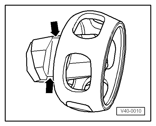
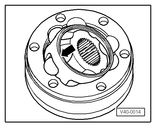
Press the ball hub and the ball cage out of the joint part -arrow-.
–
Press out the balls from the cage.
–
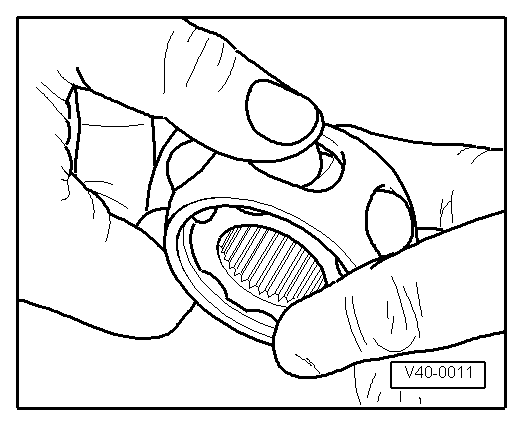
Swivel the ball hub out of the ball cage over the ball bearing track -arrows-.
–
Inspect the joint part, ball hub, ball cage and balls for small broken out depressions (pitting = point corrosion) and seizing marks.
Note
Load alteration shocks indicate too much torsional clearance in the joint. If this is the case, replace the joint. Smoothing and bearing marks do not justify a joint replacement.
Install
–
Insert the ball hub in the ball cage over the two chamfers. The fitting location is random. Press the balls into the cage.
–
Insert the hub with cage upright into the joint part.
Note
t
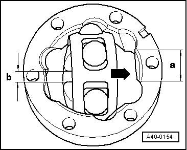
When inserting make sure the greatest distance -a- on the joint part is close to the short distance -b- on the hub after it has been swivelled in -arrow-.
t
Chamfer on inner diameter of the ball hub (serration) must point towards the largest diameter of the joint part.
–
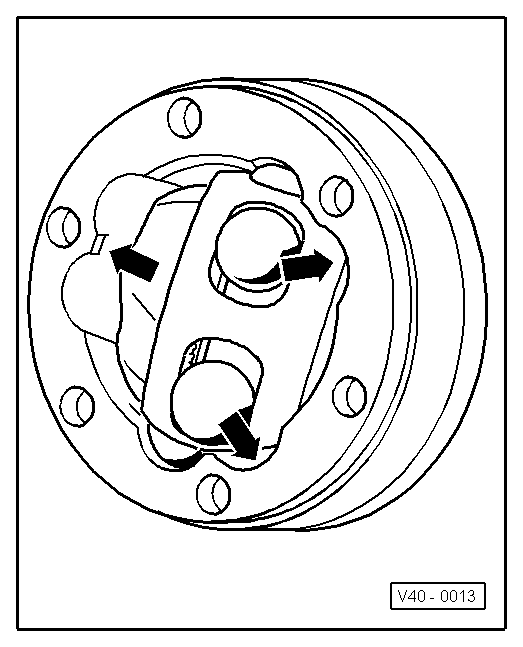
Swivel in the hub. To do so swivel the hub out of the cage -arrows- until the balls are at bearing track distance.
–
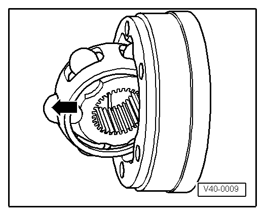
Lock the hub with the balls into position by exerting considerable pressure on the cage -arrow-.
Inspect the operation of the inner CV joint
l
The CV joint is correctly assembled if the ball hub in the joint part can be rolled by hand up and down the entire linear compensation.
–
Push the clamp and the joint boot onto the drive shaft.
–
Install drive shaft.
–
Press the specified grease quantity for the inner joint into the joint from both sides.
–
Spread the prescribed grease quantity evenly into the joint boot.
 Note
Note