| –
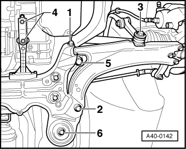
| Unscrew screws -3-, if present, at the track control arm. |
| –
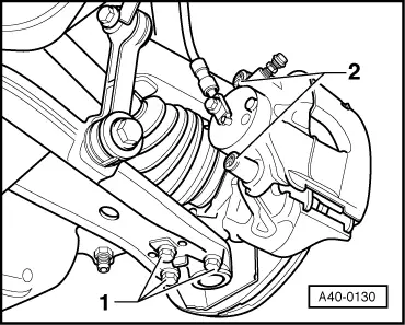
| Screw out screws -1- and -2-. |
| –
| Remove the track control arm. |
| Only for vehicles with autom. gearbox |
| –
| Release screws -4- for pendulum support. |
| –
| Unscrew screws -5- and -6- for assembly carrier. |

Note | Release the screw -1- downwards by slightly pressing the assembly carrier and take out the wheel-bearing housing. |
| (Valid for vehicles with manual and automatic gearbox). |
| Remove possible corrosion in the thread/serration of the outer joint. |
| –
| Insert track control arm and secure. |
| –
| Secure assembly carrier. |
| –
| Moisten the serration of the wheel hub with oil. |
| –
| Insert outer joint as far as possible into the serration of the wheel hub. |
| –
| Screw the steering joint and track control arm with the new screws in the former positions. |
| –
| Screw the pendulum support to the gearbox. |
| –
| If necessary, screw the coupling rod with the track control arm or with the suspension strut. |
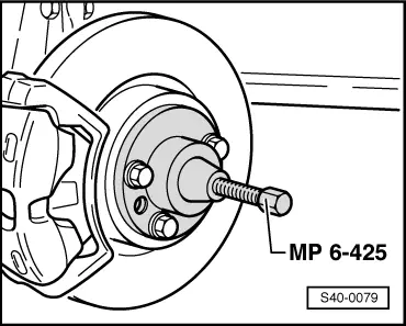
| – Moisten the contact surface of the twelve-point nut as well as the serration and the thread of the outer joint with oil and screw on new twelve-point nut as far as possible. |
| –
| Insert the outer joint into the wheel hub until the outer joint rests in the wheel bearing. |
| –
| Lower vehicle, when doing so, ensure that the wheels do not yet touch the ground. |
| If the wheel bearings are loaded through the vehicle's own weight, the wheel bearing will be initially damaged. This shortens the life of the wheel bearing. |
| –
| Depress brake pedal (assistance of second mechanic required). |
| –
| Tighten new twelve-point nut to 225 Nm and release by 1/2 a turn. |
| –
| Torque wheel hub a further min. 90°. |
| –
| Tighten twelve-point nut: |
Note |
|
|