skoda Workshop Repair Guides

Skoda Workshop Service and Repair Manuals

Disposing of the vane pump > < Vehicles with vane pump located at the top
Vehicles with vane pump located at the bottom
t  Hose clamp -MP 7-602-
t  Pliers for spring strap clamps
t  Hydraulic oil -TL52 146-, -N 052 146 00- e.g. -PENTOSIN CHF 11 S (G 002 000)-
Removing
  Note
Mark the rotation direction before removing the V-ribbed belt. Pay attention to the correct position of the V-ribbed belt in the belt pulley when installing it.
   
–  Swivel the tensioning pulley with an open-end wrench in -direction of arrow-.
–  Remove the V-ribbed belt.
The fig. shows the middle and left noise insulation on vehicles with petrol engines.
  A48-0130
–  Remove middle and right noise insulation -arrows-.
Valid for all petrol engines without air conditioning system.
Vehicles with 1.4/44 kW Engine:
–  Before removing, the fitting position of the belt pulley must be marked.
  Note
If the belt pulley of the vane pump is installed the wrong way round, it is displaced in relation to the other belt pulleys. The V-ribbed belt is damaged as a result of this displacement.
Continued for all vehicles
  A10-0161
–  Unscrew belt pulley, counterhold with Allan key (SW 9 mm).
  A48-0118
–  Pinch off the suction line - hydraulic oil reservoir/vane pump - with the hose clamp -MP 7-602-.
–  Open the spring strap clamp -3- with pliers for spring strap clamps and detach the suction line from the vane pump.
Vehicles without pressure switch (fig.)
–  Unscrew hollow screw -2- and remove pressure line (expansion hose).
Vehicles with pressure switch (without fig.)
–  Disconnect plug from pressure switch.
–  Unscrew pressure switch and remove pressure line (expansion hose).
Vehicles without and with pressure switch.
–  Screw out screws -1- and -4-.
–  Remove vane pump -5- from bracket.
Install
  Note
t  The vane pumps supplied by the spare part storeroom are without oil. Absolutely fill up with hydraulic oil before fitting -G 002 000- and turn by hand, otherwise noises or damage to the pump could occur while driving.
t  The contact surfaces and the threads on both sides of the vane pump must be free of paint.
t  Do not use drained hydraulic oil again.
t  Replace gasket rings.
  S48-0066
–  Fill the vane pump with hydraulic oil via the induction pipe -arrow B-.
–  Turn the hub of the vane pump by hand until hydraulic oil drains out of the discharge nozzle -arrow A-.
  S48-0069
–  Insert the vane pump in the bracket and screw in screws -1- and -2-.
Tightening torque: 25 Nm
Vehicles with 1.4/44 kW Engine:
  S48-0068
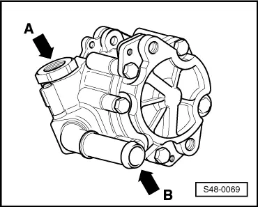
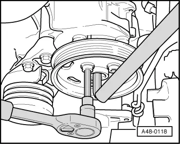
–  Screw the belt pulley to the vane pump with Allan screws according to the made marking, counterhold with Allan key (SW 9 mm).
Tightening torque: 25 Nm
  Note
If the belt pulley of the vane pump is installed the wrong way round, it is displaced in relation to the other belt pulleys. The V-ribbed belt is damaged as a result of this displacement.
Continued for all vehicles
–  Screw the belt pulley to the vane pump with Allan screws, counterhold with Allan key (SW 9 mm).
Tightening torque: 25 Nm
–  Install V-ribbed belt → Engine, Mechanics; Rep. gr.13.
  Note
t  Pay attention to the correct position of the V-ribbed belt in the belt pulley when installing it.
t  
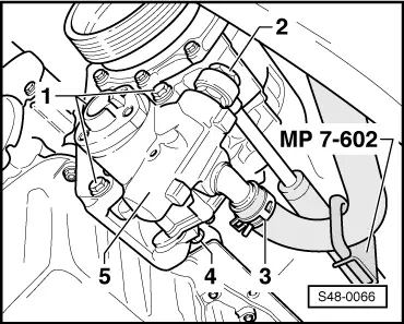
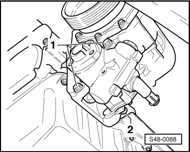
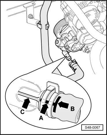
Use new gasket rings to connect the pressure line.
–  Install pressure line (expansion hose).
Tightening torque of the hollow screw or the pressure switch: 38 Nm
  A48-0118
–  Install spring strap clamp and suction line as shown in the fig.
–  The longitudinal marking -A- on the suction line must be flush with the mould joint -C- on the vane pump.
–  Fit on the spring strap clamp as far as the lateral marking -B-.
–  Remove the hose clamp -MP 7-602- from the suction line.
–  Top up with hydraulic oil and if necessary bleed the power-assisted steering system → Chapter.
–  Check line connections for tightness → Chapter.
–  Install middle and right noise insulation.
  S48-0067

Disposing of the vane pump > < Vehicles with vane pump located at the top