
Octavia Mk1
| Adjusting 2nd and 4th gear-brake -B2- on gearboxes with wave spring washer on the last outer plate |
| This setting instruction only applies to gearboxes with a wave spring washer Pos. 11 on the last outer plate Pos. 10 installed in the brake -B2-. |
 Note
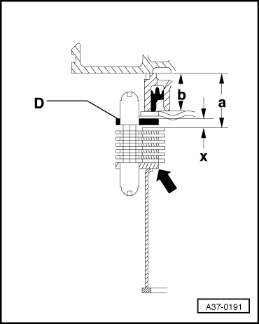
Note| t | On these gearboxes, the clearance of the brake -B2- is determined by the thickness of the adjusting washer(s). |
| t | Install components for adjustment without wave spring washer Pos. 11, without last outer plate Pos. 10 and without helical springs Pos. 6. |

| 1 - | Gearbox housing |
| 2 - | Circlip |
| q | for support pipe |
| 3 - | Support pipe -B2- |
| q | for the plate package of -B2- |
| q | different lengths, depending on the number of installed inner plates |
| q | assigned to gearbox identification characters as a spare part |
| q | insert in such a way that the groove grips into the wedge of the free wheel |
| 4 - | Outer plate -B2- |
| q | 3 mm thick |
| 5 - | Helical spring |
| q | install after installing the first outer plate Pos. 4 |
| 6 - | Helical spring |
| q | to adjust the -B2-- do not install |
| q | install before installing the last outer plate |
| 7 - | Spring |
| q | assigned to gearbox identification characters as a spare part |
| 8 - | Inner plate -B2- |
| q | Piece number → Chapter |
| q | assigned to gearbox identification characters as a spare part |
| 9 - | Outer plate -B2- |
| q | always install 2 mm thick outer plates |
| q | Piece number → Chapter |
| 10 - | Outer plate -B2- |
| q | do not install to adjust the -B2- |
| q | 2 outer plates can be installed for the adjustment. |
| 11 - | Wave spring washer |
| q | do not install to adjust the -B2- |
|
Note
|
|
|
|
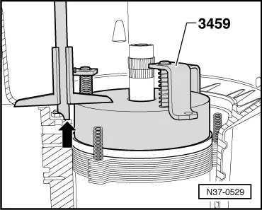
| Height of the adjusting device -3459- | = | 60.0 mm |
| - measured value | = | - 29.8 mm |
| determined value a | = | 30.2 mm |
|
|
|
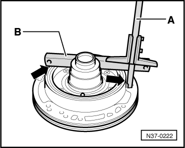
| measured value | = | 40.1 mm |
| - Straightedge | = | - 19.5 mm |
| determined value b | = | 20.6 mm |
|
| Gap size “x” (mm) | Plate (mm) |
| 4,25 … 4,49 4,50 … 4,74 4,75 … 4,99 | 2,75 3,00 3,25 |
| 5,00 … 5,24 5,25 … 5,49 5,50 … 5,74 | 3,50 3,75 2,00 + 2,00 |
| 5,75 … 5,99 6,00 … 6,24 6,25 … 6,49 | 2,00 + 2,25 2,25 + 2,25 2,25 + 2,50 |
| 6,50 … 6,74 6,75 … 7,00 | 2,50 + 2,50 2,50 + 2,75 |
|