
Octavia Mk1
 Note
Note
|
 WARNING
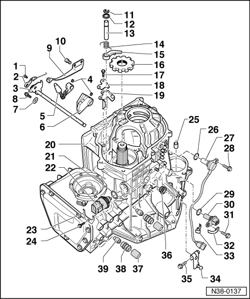
| 1 - | 4 Nm |
| q | for manuel slider lever |
| q | always replace → Electronic Catalogue of Original Parts |
| q | Replace steel spring and screw for actuation of manuel slider → Chapter |
| 2 - | Actuation of manuel slider |
| q | adjust → Chapter |
| q | Replace steel spring and screw for actuation of manuel slider → Chapter |
| 3 - | Gearshift shaft with shift segment |
| q | removing and installing → Fig. |
| 4 - | Tensioning sleeve |
| q | extracting and inserting → Fig. |
| 5 - | Engaging lever |
| q | insert together with gearshift shaft and detent segment |
| 6 - | Detent segment |
| q | insert together with gearshift shaft and engaging lever |
| 7 - | Lock washer |
| q | secures the shift shaft against wandering → Fig. |
| 8 - | 10 Nm |
| 9 - | Spring for shift segment |
| 10 - | 10 Nm |
| 11 - | Circlip |
| q | always replace → Electronic Catalogue of Original Parts |
| q | only install at axle with groove for securing ring |
| 12 - | Washer |
| 13 - | Axle for locking lever |
| q | is secured with the securing ring and the bearing cap of the input shaft |
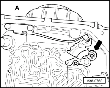
| 14 - | Retracting spring |
| q | inserting → Fig. |
| 15 - | Locking lever |
| q | insert with retracting spring → Fig. |
| 16 - | Parking position gear |
| q | the rounded side points to the serration of the input shaft |
| 17 - | 14 Nm |
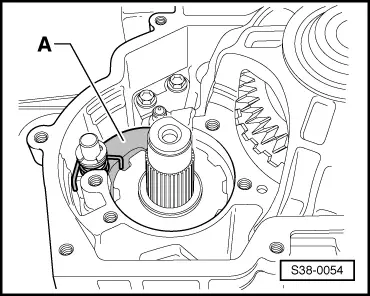
| 18 - | Support plate |
| q | installing → Fig. |
| 19 - | Guide plate |
| q | insert in front of the support plate Pos. 18 → Fig. |
| 20 - | Gearbox housing |
| q | the drive gear must not be removed to disassemble the parking lock |
| 21 - | O-ring |
| q | always replace → Electronic Catalogue of Original Parts |
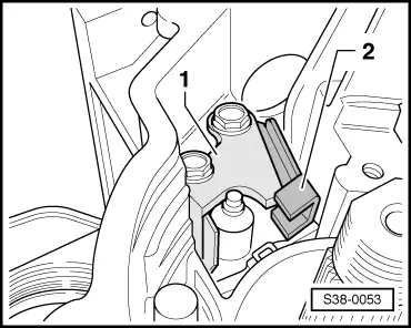
| 22 - | Multi-function switch -F125- |
| q | is checked by self-diagnosis → Chapter |
| q | remove before disassembling the shift shaft Pos. 3 |
| q | removing and installing → Fig. |
| 23 - | Support |
| q | for multi-function switch |
| 24 - | 10 Nm |
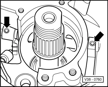
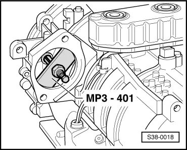
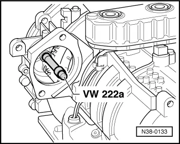
| 25 - | Bushing for starter |
| q | removing → Fig. |
| q | inserting → Fig. |
| 26 - | O-ring |
| q | always replace → Electronic Catalogue of Original Parts |
| 27 - | Vehicle speed sender -G68- |
| q | is checked by self-diagnosis → Chapter |
| q | adhering dirt impairs the operation, clean if necessary |
| q | removing and installing → Chapter |
| 28 - | 10 Nm |
| 29 - | O-ring |
| q | always replace → Electronic Catalogue of Original Parts |
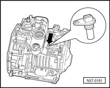
| 30 - | Gearbox speed sender -G38- |
| q | is checked by self-diagnosis → Chapter |
| q | adhering dirt impairs the operation, clean if necessary |
| q | removing and installing → Fig. |
| 31 - | 10 Nm |
| 32 - | Retaining clip |
| q | for cable to vehicle speed sender -G68- |
| q | fasten with screw Pos. 31 |
| 33 - | Retaining clip |
| q | for cable of vehicle speed sender -G68- |
| q | press onto gearbox reinforcing rib |
| 34 - | Lever |
| q | for gearshift shaft |
| 35 - | 10 Nm |
| 36 - | Gasket ring |
| q | release with a screwdriver |
| q | drive in using a pipe section -MP3-479 (VW 423)- until flush |
| 37 - | Ventilation cap |
| 38 - | Bleeding (of air) |
| 39 - | Ventilation tube |
| q | remove with pliers |
| q | drive in up to the stop with the drift -MP3-481/2 (VW 460/2)- |
|
|
|
|
|
|
Note
|

|
Note
|
|
|
|
|
|