
Octavia Mk1
 Note
Note
|

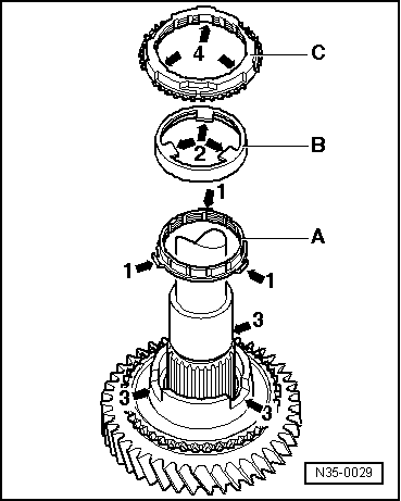
| 1 - | Nut, 25 Nm + 90° |
| q | 4 nuts for bearing support |
| q | always replace |
| 2 - | Clutch housing |
| 3 - | Adjusting washer |
| q | Determining thickness ⇒ - Setting output shaft → Chapter |
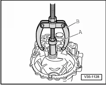
| 4 - | Outer ring/tapered-roller bearing small |
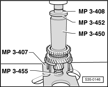
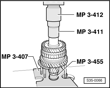
| q | removing → Fig. |
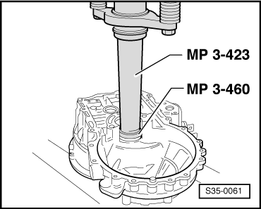
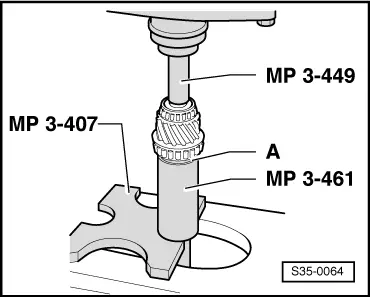
| q | pressing on → Fig. |
| 5 - | Inner ring/tapered-roller bearing small |
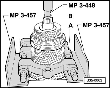
| q | remove → Fig. |
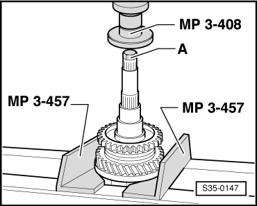
| q | pressing on → Fig. |
| 6 - | Output shaft |
| q | is paired with the gear pinion of the final drive, replace together |
| q | adjust → Chapter |
| 7 - | Inner ring/tapered-roller bearing large |
| q | remove → Fig. |
| q | pressing on → Fig. |
| 8 - | Gasket ring |
| q | Insert gasket rings (4 pieces) on the bearing support screws |
| 9 - | Bearing support |
| q | with outer ring/tapered-roller bearing large and screws |
| q | Always replace outer ring together with tapered-roller bearing large and bearing support |
| 10 - | Thrust washer |
| q | Heel of thrust washer points to tapered-roller bearing |
| 11 - | 1st gear sliding gear |
| 12 - | Needle bearing |
| q | 1st gear |
| q | Dimensions 38 x 43 x 25 |
| 13 - | 1st gear synchronizer ring |
| q | for gearbox ? 08.00 |
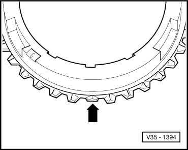
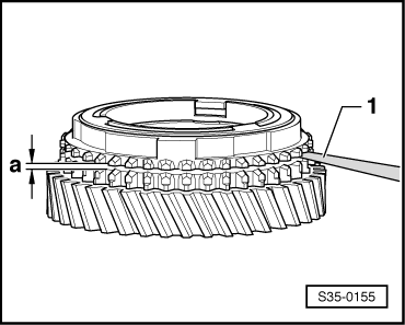
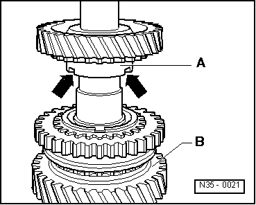
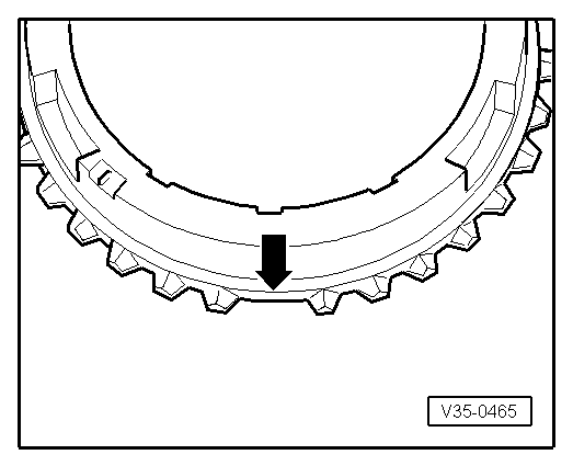
| q | check for wear → Fig. |
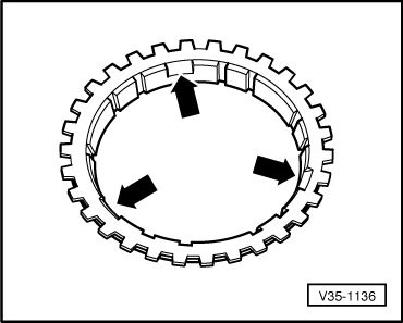
| q | Identification → Fig. |
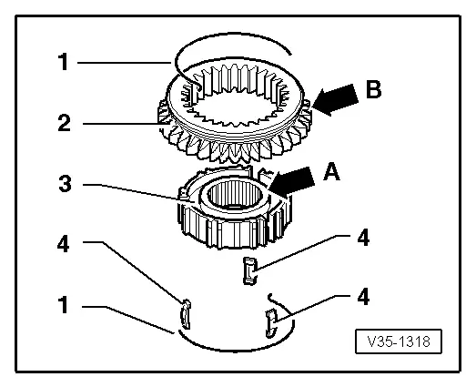
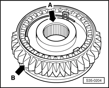
| 14 - | Inner ring for 1st gear |
| q | for gearbox 08.00 ? |
| q | check for wear → Fig. |
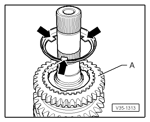
| q | Check pegs for traces of wear |
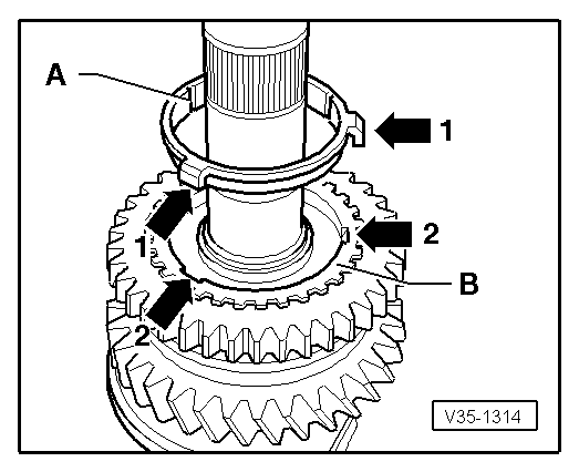
| q | Fitting position → Fig. |
| 15 - | Outer ring for 1st gear |
| q | for gearbox 08.00 ? |
| q | fit on inner ring (⇒ Pos. 14), fitting position → Fig. |
| q | replace if there are any traces of scoring or of friction |
| 16 - | 1st gear synchronizer ring |
| q | for gearbox 08.00 ? |
| q | Identification → Fig. |
| q | check for wear → Fig. |
| q | Fitting position → Fig. |
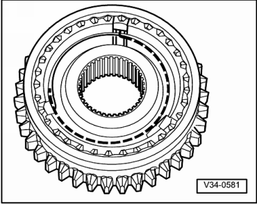
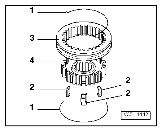
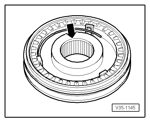
| 17 - | Sliding sleeve with 1st and 2nd gear synchronizer body |
| q | after removing the circlip (⇒ Pos. 18) pull over bearing support → Fig. |
| q | disassembling → Fig. |
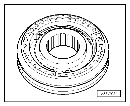
| q | Assembling sliding sleeve/synchronizer body → Fig. and → Fig. |
| q | Fitting position ? 08.00 → Fig. |
| q | Fitting position 08.00 ? → Fig. |
| q | pressing on → Fig. |
| 18 - | Circlip |
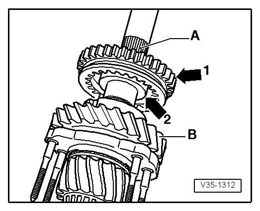
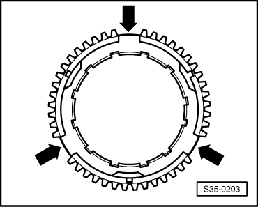
| 19 - | 2nd gear synchronizer ring |
| q | Identification ? 08.00 → Fig. |
| q | Identification 08.00 ? → Fig. |
| q | check for wear → Fig. |
| q | insert in such a way that the recesses lock into the arresters of the synchronizer body ⇒ Pos. 17 |
| 20 - | Outer ring for 2nd gear |
| q | fit into synchronizer ring (⇒ Pos. 19), fitting position → Fig. |
| q | replace if there are any traces of scoring or of friction |
| 21 - | Inner ring of 2nd gear |
| q | check for wear → Fig. |
| q | Check pegs for traces of wear |
| q | Fitting position → Fig. |
| 22 - | 2nd gear sliding gear |
| q | Fitting position → Fig. |
| 23 - | Needle bearing |
| q | 2nd gear |
| q | Dimensions 35 x 40 x 23.8 |
| 24 - | Thrust washer |
| q | Dimensions 30.8°x°52 x°3.5 |
| 25 - | Bushing for 3rd gear needle bearing |
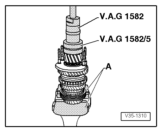
| q | press off with 2nd gear sliding gear → Fig. |
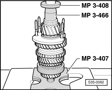
| q | pressing on → Fig. |
| q | Dimensions 30.6 x 35 x 25.85 |
| 26 - | Needle bearing |
| q | 3rd gear |
| q | Dimensions 35 x 39.6 x 25.5 |
| 27 - | 3rd gear sliding gear |
| 28 - | 3rd gear synchronizer ring |
| q | check for wear → Fig. |
| 29 - | Sliding sleeve with 3rd and 4th gear synchronizer body |
| q | press off together with 2nd gear (⇒ Pos. 22) and 3rd gear (⇒ Pos. 27) sliding gear → Fig. |
| q | disassembling → Fig. |
| q | Fitting position sliding sleeve/synchronizer body → Fig. |
| q | Assembling sliding sleeve/synchronizer body → Fig. and → Fig. |
| q | pressing on → Fig. |
| 30 - | Bushing |
| q | for needle bearing |
| q | press off together with sliding sleeve and 3rd and 4th gear synchronizer body (⇒ Pos. 29) → Fig. |
| q | pressing on → Fig. |
| q | Dimensions 29 x 35 x 24.1 |
| 31 - | Needle bearing |
| q | 4th gear |
| q | Dimensions 35 x 40 x 23.8 |
| 32 - | 4th gear synchronizer ring |
| q | check for wear → Fig. |
| 33 - | 4th gear sliding gear |
| 34 - | Thrust washer |
| q | Dimensions 29,2 x 49 x 2,5 |
| 35 - | Needle bearing |
| q | for output shaft |
| q | removing and installing → Chapter |
| 36 - | Gearbox housing |
| 37 - | Bushing |
| q | for needle bearing of output shaft |
| q | pressing off → Fig. |
| q | pressing on → Fig. |
| q | Dimensions 29 x 34 x 18.15 |
| 38 - | 5th gear sliding gear |
| q | removing and installing → Chapter |
| 39 - | Disc spring |
| q | Fitting position → Chapter |
| 40 - | 80 Nm + torque a further 90° |
| q | holds the disc spring in position |
| q | always replace |
|
|
|
|
|
|
|
|
|
|
|
|
|
|
|
|
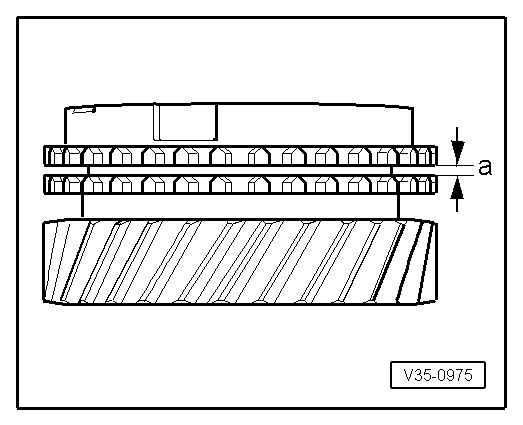
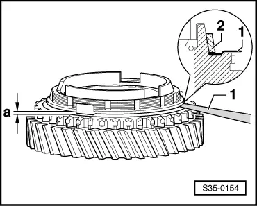
| Fitting dimension | Wear limit | |||
| Clearance -a- | 1,0 ... 1.7 mm | 0.5 mm | ||
|
|
|
|
|
|
Note
|
|
|
|
|
|
|
|
| Fitting dimension | Wear limit | |||
| Clearance -a- | 0,75 ... 1.25 mm | 0.3 mm | ||
|
|
| Fitting dimension | Wear limit | |||
| Clearance -a- | 1,2 ... 1.8 mm | 0.5 mm | ||
|
|
|
|
|
|
|
|
|
|
|
|
|
|
|
|
|
|
|
|
|
|
|
|
|
|
|
|