Octavia Mk2
| Summary of components of lubrication system |
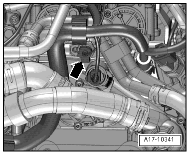
| Fitting location of the oil pressure switch -F1- and tightening torque → Fig. |

| 1 - | Dipstick |
| q | oil level must not exceed max. marking! |
| 2 - | Engine oil cooler |
| q | removing and installing → Chapter |
| 3 - | O-ring |
| q | replace |
| 4 - | Coolant pipe |
| q | for engine oil cooler |
| q | Tightening torque bracket to the cylinder block: 20 Nm |
| 5 - | 8 Nm |
| 6 - | Screw cap |
| q | Replace seal if damaged |
| 7 - | Sealing ring |
| q | replace if damaged |
| 8 - | Oil filter, 20 Nm |
| q | with gasket rings |
| q | with non-return valve |
| q | slacken and tighten with oil filter wrench -3417- |
| q | Keep to change intervals → Octavia II |
| 9 - | Timing case |
| q | Removing and installing the timing case → Chapter |
| 10 - | 10 Nm |
| 11 - | 150 Nm + torque a further 180° (1/2 turn) |
| q | replace |
| q | removing and installing → Chapter „Removing and installing crankshaft-belt pulley“ |
| q | The clamping surface of the fixing screw must be free of grease and oil. |
| q | insert oiled (thread) |
| q | Secure belt pulley with counterholder -T30004 (3415)- to prevent it from turning |
| 12 - | Belt pulley |
| q | removing and installing → Chapter |
| q | Clamping surfaces must be free of oil and grease. |
| q | Secure belt pulley with counterholder -T30004 (3415)- to prevent it from turning |
| q | Removing and installing ribbed V-belt → Chapter |
| 13 - | Sealing ring |
| q | replace |
| 14 - | Bushing |
| q | The clamping surfaces of the bushing must be free of grease and oil. |
| 15 - | Gasket |
| q | replace if damaged |
| 16 - | Sprocket |
| q | removing and installing → Chapter |
| q | for oil pump drive |
| 17 - | 20 Nm + torque a further 1/4 turn (90°) |
| q | replace |
| 18 - | Sprocket |
| q | removing and installing → Chapter |
| q | for oil pump |
| q | counterhold with counterholder -T10172- |
| 19 - | Drive chain |
| q | removing and installing → Chapter |
| q | for oil pump |
| q | mark running direction (installed position) before removing |
| 20 - | 10 Nm |
| 21 - | Oil level and oil temperature sender -G266 - |
| q | replace if damaged |
| q | check: → Current flow diagrams and Fitting locations |
| 22 - | Oil drain plug, 30 Nm |
| q | with captive seal |
| q | replace |
| 23 - | 13 Nm |
| q | replace |
| q | slacken and tighten only the bolts at the gearbox side with socket insert -T10058- |
| 24 - | 40 Nm |
| 25 - | Oil pan |
| q | removing and installing → Chapter |
| 26 - | 25 Nm |
| 27 - | Oil pump |
| q | must be replaced completely |
| 28 - | 5 Nm |
| 29 - | Oil separator |