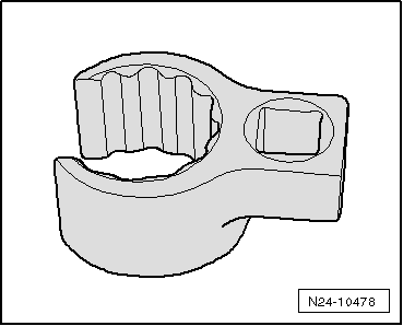
skoda Workshop Repair Guides

Skoda Workshop Service and Repair Manuals

Engine control unit > < Check fuel pressure sender G247
Removing and installing fuel pressure senderG247
Removing and installing fuel pressure sender -G247-
Special tools and workshop equipment required
t  Assembly device -T10118-
   
t  Open ring spanner with 3/8" drive, wrench size 27 mm
Removing
  Note
t  Safety precautions when working on the fuel supply system → Chapter.
t  Rules of cleanliness when working on the fuel supply system → Chapter.
–  Switch off the ignition and all electrical components and take out the ignition key.
  WARNING
The injection system consists of a high pressure part (max. pressure of 12 MPa = 120 bar) and a low pressure part (pressure of approx. 0.6 MPa = 6 bar).
t  Before opening the high pressure area, e.g. removing the high pressure pump, the fuel distributor, the injection valves, the fuel pipes or the fuel pressure sender -G247-, the fuel pressure in the high pressure area with a remaining pressure of approx. 0.6 MPa (6 bar) must be reduced.
t  The procedure for this is described in the chapter “release pressure in the high pressure area of the fuel system” → Chapter.
  N24-10478
–  Release screws -2- and remove retaining clip -1-.
–  Disconnect plug -3- from charge pressure sender -G31- with intake air temperature sender 2 -G299-.
–  Unhook the hoses at the pressure pipe and open the cable guide.
–  Press the retaining clips -arrows- towards the outside and pull the pressure pipe out towards the top.
–  Then pull off the pressure pipe from the exhaust turbocharger.
  Note
Hold the screwed connections at the high pressure pump and at the bottom part of intake manifold/fuel distributor when unscrewing the union nuts with a wrench.
  A21-10169
–  Unscrew union nuts -arrows- and screw -1- and remove high pressure line.
  Note
t  The bracket for the fuel lines must on no account be bent up.
t  If the bracket is bent up or the fuel line is replaced, the bracket must also be replaced.
  A15-10540
–  Release the plug from the fuel pressure sender -G247--2- with the assembly tool -T10118 -.
–  Screw out fuel pressure sender -G247- with open ring spanner with 3/8" drive, wrench size 27 mm.
–  Collect the fuel which flows out with a cleaning cloth.
Install
Installation is carried out in the reverse order. However, pay attention to the following:
t  Tightening torques: → Chapter
  A24-10571

Engine control unit > < Check fuel pressure sender G247