skoda Workshop Repair Guides

Skoda Workshop Service and Repair Manuals

Removing and installing the sender for the fuel gauge display G > < Removing and installing the fuel tank
Removing and installing the fuel delivery unit
Special tools and workshop equipment required
t  Key -T30101 (3087)-
Removing
l  The fuel tank must not be more than 3/4 full.
  Note
t  Empty the fuel tank → Chapter if necessary.
t  Observe the safety instructions before starting fitting work → Chapter.
t  Observe rules for cleanliness → Chapter.
–  Switch off the ignition and all electrical components and take out the ignition key.
–  Removing rear seat bench → Body Work → Rep. Gr.72.
   
–  Unclip cover -4- with fuel pump control unit -J538--1-.
  Note
For vehicles with auxiliary heating, the plug connection for the dosing pump -V54- must be disconnected additionally.
  S20-0159
–  Unplug the 5-pin connector, the black feed line -1- and the blue return-flow line -2-.
  Note
t  Press in securing ring in order to unlock the lines.
t  For vehicles with auxiliary heating the suction line for the dosing pump -V54- must be pulled out additionally (open lower clamp).
  S20-0334
–  Open the lock ring with the wrench -T30101-.
  Note
t  Take the fuel delivery unit out of the fuel tank in such a way that the electrical cables and the fuel hoses are not damaged and that the float arm of the sender for the fuel gauge display -G- is not bent.
t  You must empty the old fuel delivery unit before disposing of it if you wish to replace the fuel delivery unit.
–  Pull the fuel delivery unit out of the opening of the fuel tank.
Install
Installation occurs in reverse order. Pay attention to the following:
–  Insert the new dry gasket ring of the flange into the opening of the fuel tank and moisten only from the inside with fuel for installing the closing flange.
–  Insert the fuel delivery unit into the fuel tank in such a way that the float arm of the sender for the fuel gauge display -G- is not bent.
–  Press the closing flange downwards, install the lock ring and connect the fuel lines.
  Note
  S20-0160
t  
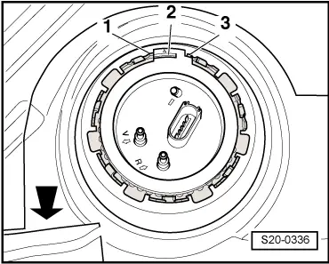
Pay attention to installed position of flange of fuel delivery unit: The peg -2- on the fuel delivery unit must be located between the pegs -1- and -3-. The -arrow- shows the direction of travel.
t  
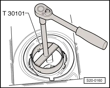
Tighten the lock ring to 110 Nm.
t  
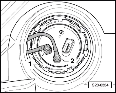
Do not interchange the black feed line and the blue return-flow line (arrows on the flange of the fuel delivery unit).
t  
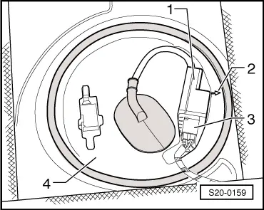
Make sure the line connections fit tightly and the 5-pin connector fit tightly.
t  After installing the fuel delivery unit, check whether the feed and return-flow line is still clipped in place on the fuel tank.
t  If the fuel delivery unit was replaced on vehicles with the fuel pressure sender for low pressure -G410 - ( → Chapter, position 4), adapt the engine control unit to the fuel pump → Vehicle diagnosis, testing and information system VAS 5051. On vehicles without the fuel pressure sender for low pressure -G410-, the adaptation is performed automatically while driving.
  S20-0336
–  Install cover -4- with fuel pump control unit -J538--1-.
   The arrow -2- on the cover points in direction of travel.
  S20-0159

Removing and installing the sender for the fuel gauge display G > < Removing and installing the fuel tank