skoda Workshop Repair Guides

Skoda Workshop Service and Repair Manuals

Air filter - Summary of components > < Fuel rail with injection valves - Summary of components
Removing and installing fuel distributor (bottom part of intake manifold)
Special tools and workshop equipment required
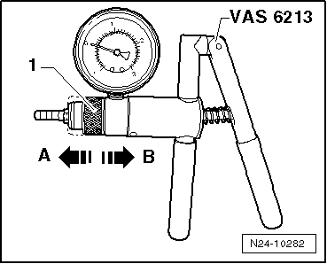
t  Hand vacuum pump, e.g. -VAS 6213- or -V.A.G 1390-
t  Drill Ø 2.5 mm
Removing
  WARNING
Reduce the pressure in the high pressure part of the fuel system → Chapter.
–  Remove the intake manifold → Chapter.
   
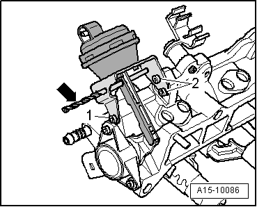
–  Push the actuator rod of the vacuum setting element for intake manifold in direction of setting element and lock with a 2.5 mm -arrow- drill Ø.
  A15-10086
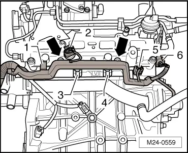
–  Separate the electric plug connections -1- to -6-.
–  Turn the screws -arrows- and remove the cable guide.
  M24-0559
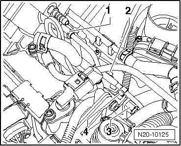
–  Unscrew the screw -2- of the cable guide and remove the clip -4- from the high pressure line.
  Note
Counterhold the screw neck in the high pressure pump and in the fuel distributor (bottom part of intake manifold) when loosening the union nuts of the high pressure line using a wrench.
–  Unscrew the union nuts -1- and -3- of the high pressure line.
  N20-10125
–  Disconnect the fuel feed line -2- at the fuel distributor.
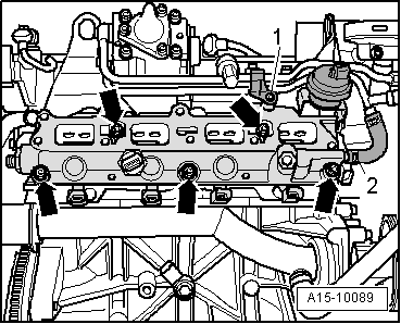
–  Unscrew the screws -arrows- and detach the fuel distributor.
–  Removing and installing injection valves → Chapter.
Install
  Note
Replace gaskets and O-rings.
  A15-10089
l  The actuator rod of the vacuum setting element for intake manifold flap must be locked with a Ø 2.5 mm -arrow- drill.
–  The intake manifold flap must be slightly raised when positioning the fuel distributor on the cylinder head.
  Note
Non compliance may get the intake manifold flap stuck between fuel distributor and cylinder head so that actuation in the assembled state is no longer possible.
  A15-10086
–  Tighten the fuel distributor -arrows-.
–  Connect up the fuel feed line -2-.
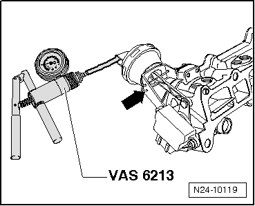
–  Test the operation of the intake manifold flap with the hand vacuum pump -VAS 6213-.
  A15-10089
–  Connect the hand vacuum pump -VAS 6213 - as shown.
–  Pull out the drill or the retaining clip -arrow-.
  N24-10119
–  Put the switch-over ring -1- of the hand vacuum pump -VAS 6213- in position -A- for “vacuum”.
–  Generate vacuum and test the operation of the vacuum setting element for intake manifold at the actuator rod.
  N24-10282
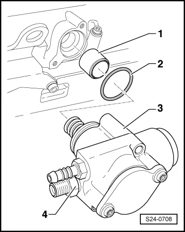
–  Check that the screw neck -4- in the high pressure pump has a tightening torque of 40 Nm.
–  Install high pressure line → Chapter.
Further installation occurs in reverse order to removal.
  S24-0708

Air filter - Summary of components > < Fuel rail with injection valves - Summary of components