skoda Workshop Repair Guides

Skoda Workshop Service and Repair Manuals

Removing and installing engine trim panel > < Removing and installing engine
Removing engine
Removing engine
Special tools and workshop equipment required
t  Catch pan for workshop crane, e.g. -VAS 6208-
t  
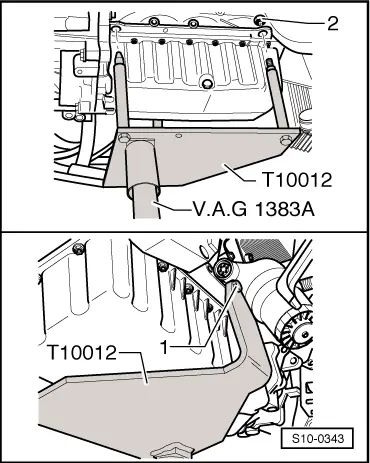
Engine and gearbox jack, e.g. -V.A.G 1383 A-
t  Engine mount -T10012-
t  Workshop crane, e.g. -VAS 6100-
t  Double ladder, e. g. -VAS 5085-
t  Hose clamps up to Ø 25 mm -MP7-602 (3094)-
t  Pliers for spring strap clamps
–  Before removing the engine, interrogate the fault memory of all control units → Vehicle diagnosis, testing and information system VAS 5051.
  Note
t  The engine is removed downwards together with the gearbox.
t  All cable straps that have been loosened or cut open when the engine was removed must be fitted again in the same location when the engine is installed again.
t  Leave the car key in the ignition lock so that the steering wheel lock does not click into place.
t  Collect drained coolant in a clean container for reuse or proper disposal.
  Caution
Please observe the following when undertaking all assembly work, particularly in the engine compartment, due to its cramped construction.
t  Lay lines of all kinds (e.g. for fuel, hydraulic fluid, cooling fluid and refrigerent, brake fluid, vacuum) and electrical lines in such a way that the original line guide is re-established.
t  In order to avoid damage to the cables, ensure that there is adequate free access to all moving or hot components.
Observe all safety measures and notes for assembly work on the fuel and injection system, the charge air system as well as the rules for cleanliness → Chapter.
–  Remove engine cover → Chapter.
–  Before disconnecting the battery, if necessary remove the adapter for the safety wheel bolts from the luggage compartment.
  WARNING
Observe measures when disconnecting the battery → Electrical System → Rep. Gr.27.
–  Disconnect the battery-earth strap with the ignition off → Electrical System → Rep. Gr.27.
–  Remove plenum chamber cover and bulkhead plenum chamber → Body Work → Rep. Gr.66.
–  Remove air filter with air mass meter, air intake hose and suction hose.
t  Vehicles with engine identification characters BKD, AZV: → Chapter
t  Engine identification characters BMM: → Chapter
–  Remove battery and battery tray → Electrical System → Rep. Gr.27.
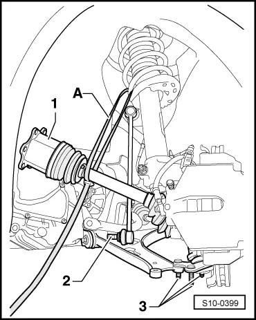
–  Slacken the screw for the front right drive shaft only by maximum 90°, otherwise the wheel bearing may be damaged.
–  Remove both front wheels → Chassis → Rep. Gr.44.
–  Remove noise insulation → Body Work → Rep. Gr.50.
–  Remove the right wheelhouse liner bottom part → Body Work → Rep. Gr.66.
–  Remove right drive shaft → Chassis → Rep. Gr.40.
–  Remove the left drive shaft from the gearbox flange.
   
–  Unscrew the nut from the left coupling rod -2- of the anti-roll bar and press the coupling rod off the anti-roll bar.
–  Unscrew the nuts from the left steering joint -3- and press the steering joint out of the suspension arm.
–  If present, remove coupling rod from front left vehicle level sensor -G78-.
–  Turn steering to full left lock.
–  Swivel the steering joint outwards and secure the drive shaft -1- with a band -A- in the wheel housing as shown in the illustration.
–  Insert the steering joint to ensure stabilisation with a threaded bore into the suspension arm.
  WARNING
Hot steam or hot coolant may escape when the coolant expansion reservoir is opened. Cover the cap with a cloth and open carefully.
–  Draining coolant.
t  Vehicles with engine identification characters BKD, AZV: → Chapter
t  Engine identification characters BMM: → Chapter
  S10-0399
–  Detach coolant hose, fuel intake hose -2- and fuel return-flow hose -1- from pipes at cylinder head.
Vehicles up to 08.05
  S10-0359
–  Unlatch fuse, remove fuel filter with its connected hoses upwards from bracket -arrow- and lay to the side.
Vehicles as of 08.05
  S10-0305
–  Release screw -1- by one turn.
–  Release screw -2- and nut -3-.
–  Take out fuel filter with connected hoses and lay to the side.
Continued for all vehicles
–  Remove V-ribbed belt → Chapter.
–  Remove alternator → Electrical System → Rep. Gr.27.
Vehicles with air conditioning
  WARNING
Refrigerant circuit of the air conditioning system must not be opened.
  Note
To avoid causing damage to the AC compressor as well as to the refrigerant lines and hoses make sure the lines and hoses are not over-extended, kinked or bent.
–  Remove AC compressor from the bracket for auxiliary units → Chapter.
–  Tie up removed AC compressor with connected refrigerant hoses to the body.
Vehicles with auxiliary heating.
–  Disconnect necessary connections at the coolant pipes and at the coolant shut-off valve of heating system -N279-.
–  Only remove long exhaust pipe of auxiliary heating → Heating, Air Conditioning → Rep. Gr.82.
Continued for all vehicles
–  Remove charge air hoses and charge air pipe between engine and charge air cooler.
t  Engine identification characters BKD, AZV: → Chapter
t  Engine identification characters BMM: → Chapter
  Caution
Shut off the openings of the charge air cooler, e.g. with a clean foam piece, so that no coolant can penetrate.
–  Remove fan shroud and radiator.
t  Engine identification characters BKD, AZV: → Chapter
t  Engine identification characters BMM: → Chapter
–  Remove the bracket for the wiring of the oil level and oil temperature sender -G266- from the assembly carrier.
  A20-10245
–  First of all release the screw -1-.
–  Then release the screws -2- and -3- and remove the pendulum support.
Vehicles with four-wheel drive
–  Remove assembly carrier without steering gear → Chassis → Rep. Gr.40.
–  Disconnect propshaft from gearbox → Gearbox → Rep. Gr.39.
Continued for all vehicles
  Caution
The decoupling element in the pre-exhaust pipe should not be bent by more than 10° - danger of damaging it.
–  Remove the pre-exhaust pipe from the exhaust turbocharger → Chapter.
–  Unlatch the fuse and disconnect the front plug from the engine control unit → Chapter.
  S10-0269
–  Release duct for engine wiring harness -arrow- and pull out upwards.
  S10-0319
–  Open the cable guide -arrows-, remove the engine wiring harness and place down to the side.
–  Release all remaining plugs at engine and gearbox and lay aside the relevant lines.
  Note
To release the plug of the engine speed sender -G28-, press the plug together with a screwdriver and at the same time raise the release button with a thin wire hook.
–  Detach all connecting, coolant and vacuum hoses from the engine.
Vehicles fitted with a manual gearbox
–  Remove the gearshift mechanism from the gearbox → Gearbox → Rep. Gr.34.
–  Remove the pressure line at the breather/slave cylinder of the clutch control → Gearbox → Rep. Gr.30.
  WARNING
After separating the hydraulic line, do not operate the clutch pedal.
Vehicles with automatic gearbox
–  Remove the gearshift mechanism from the gearbox → Gearbox → Rep. Gr.34.
Continued for all vehicles
  S10-0245
–  Screw engine mount -T10012- to the cylinder block with nut -2- and screw -1- to 20 Nm.
–  Insert engine/gearbox jack -V.A.G 1383 A- in the engine mount and slightly raise.
  WARNING
Use double ladder to release the screws for the engine and gearbox mounting.
  S10-0343
–  Successively release screws for engine mounting -arrows-.
  S10-0267
–  Successively release screws for gearbox mounting -arrows-.
  Note
t  Check whether all hose and line connections between engine, gearbox and body are released.
t  When lowering carefully guide the engine with the gearbox, in order to avoid damage.
–  Carefully lower engine with gearbox.
–  Remove the gearbox from the engine → gearbox → Rep. Gr.34.
  S10-0358

Removing and installing engine trim panel > < Removing and installing engine