
Octavia Mk2
| Connection diagram for vacuum hoses for engine with engine identification characters BMM |
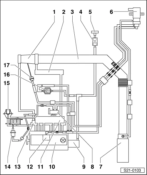
| 1 - | Exhaust gas turbocharger |
| 2 - | Charge air cooler |
| 3 - | Inlet hose |
| 4 - | Non-return valve |
| 5 - | Brake servo unit |
| 6 - | Solenoid valve for charge pressure control -N75- |
| 7 - | Air filter |
| 8 - | Changeover valve for radiator of exhaust gas recirculation -N345- |
| 9 - | Tandem pump |
| 10 - | Cylinder head |
| 11 - | Intake manifold |
| 12 - | Vacuum reservoir |
| 13 - | Exhaust pipe |
| 14 - | Vacuum setting element |
| q | the radiator flap for exhaust gas recirculation |
| q | always replace together with radiator for exhaust gas recirculation |
| 15 - | electrical exhaust gas recirculation valve -N18- with EGR potentiometer -G212- and EGR control motor -V338- |
| 16 - | Non-return valve |
| q | white connection points to charge pressure control solenoid valve (Position 6) and to vacuum reservoir |
| 17 - | Vacuum setting element |
| q | for charge pressure control |
| q | part of turbocharger, cannot be replaced separately |