| –
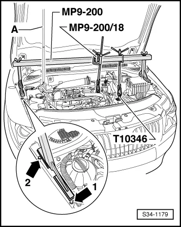
| Screw the bracket -T10346- to the rear opening of the three openings in the battery tray. |
| –
| To do so, use a collar screw M6 or one of the fixing screws for the battery tray. |
| –
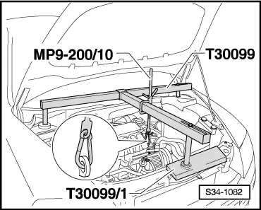
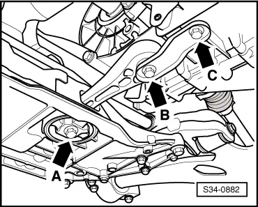
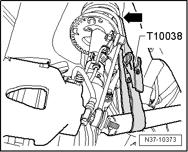
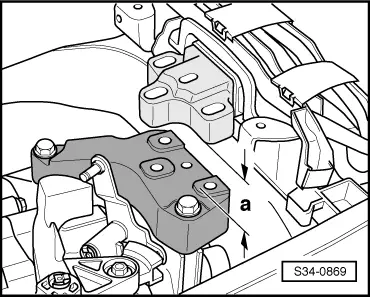
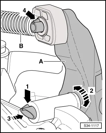
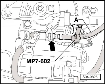
| Position the supporting device -MP9-200 (10 - 222 A)- behind the pressurized gas strut -A- for the front flap. |
| –
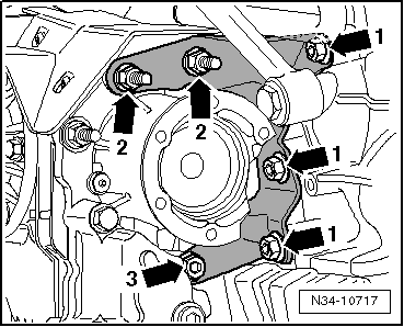
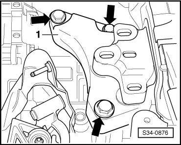
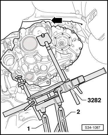
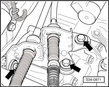
| Place the feet of the supporting device, as shown in the illustration, behind the screw -arrow 1- and sideways up to the screw -arrow 2- on the wheelhouse frame side rail at the top. |
| –
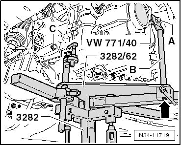
| Connect the holder -T10346- with the supporting device. |
| –
| Hook the second spindle into the front left engine lifting eye. |
| –
| Slightly take up the weight of the engine/gearbox unit via the spindle, do not raise. |
| –
| Loosen the wheel bolts on front left and front right. |
| –
| Remove wheels at the front. |
| –
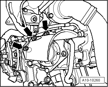
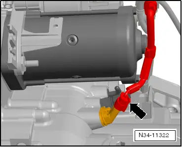
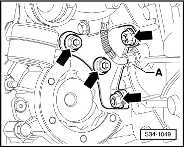
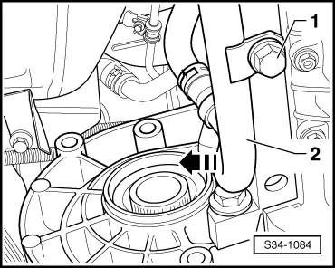
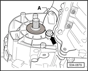
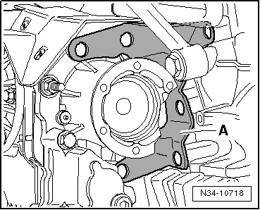
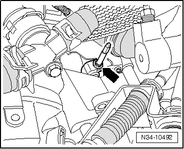
| Unscrew bracket from starter. |
|
|
|

 Note
Note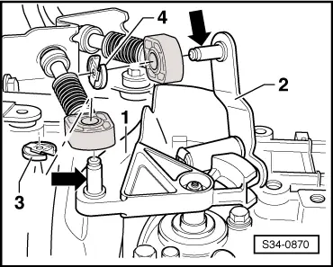
 Caution