skoda Workshop Repair Guides

Skoda Workshop Service and Repair Manuals

Summary of components - Control cables up to 10.06 > < Dismantling
Assembling together
Assembling together
  Caution
The lower leg of the pressure spring ( → Anchor) can jump off uncontrolled from the shoulder of the selector angle during further handling.
–  Thus carefully press down the lower leg from the shoulder of the selector angle plate.
The legs of the pressure spring tighten „crosswise“ with a loud noise
   
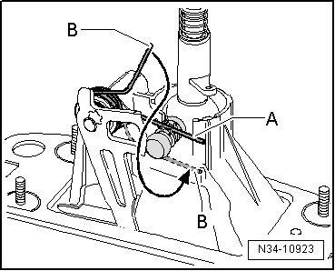
–  To slacken, turn around the legs of the pressure spring -A- and -B- towards the right.
l  The legs -A- and -B- must point in the opposite direction. Shown here for inserted shift lever guide.
  N34-10923
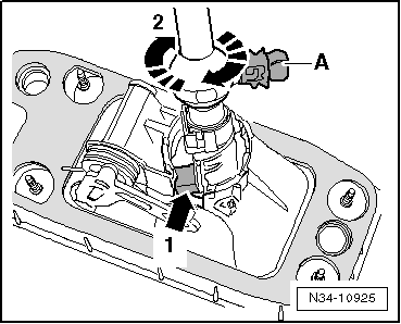
–  Insert shift lever guide with shift lever into the shift housing.
l  The stud -arrow 1- is still located in the recess of the shift housing.
–  Turn shift lever guide in -direction of arrow 2-, until the ball stud -A- is above the recess of the shift housing.
  N34-10925
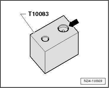
–  Position shift housing with shift lever guide into the larger recess -arrow- of the Insert base - T10083-.
  Note
If necessary, first of all remove the shift lever so that the shift housing with shift lever guide can be inserted in the insert base.
  N34-10869
l  The shift lever guide must protrude out of the shift housing as far as the stop.
–  Insert the leg -A- of the pressure spring from the top into the guide.
–  Pull leg -B- of pressure spring downwards and insert the leg -B- next to the guide (in direction of the spherical head).
  Note
To provide a clearer illustration, only the selector angle plate is partially illustrated.
–  Carefully remove shift housing with shift lever guide from the insert base - T10083-.
  N34-10923
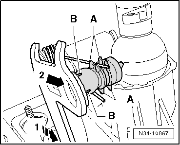
–  Move selector angle plate up to stop to the rear (opposite the location holes for shift and selector cable) -direction of arrow 1-.
–  Grease the ball stud with grease -G 000 450 02-.
–  Press the ball stud into the selector angle plate -arrow 2-.
l  The guides -A- and the tabs -B- must not be damaged.
  N34-10867
–  Position shift housing with shift lever guide into the larger recess -arrow- of the Insert base - T10083-.
  N34-10869
l  The shift lever guide must protrude out of the shift housing as far as the stop.
–  Lift the upper leg -A- of the pressure spring over the stud of the selector angle plate.
l  Use a new bearing shell -B-.
–  Grease the bearing shell and the bearing ball of the shift lever guide with grease -G 000 450 02-.
–  Press the bearing shell up to stop onto the bearing ball of the shift lever guide.
–  Remove shift housing from the insert base -T10083-.
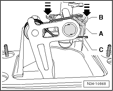
–  Press the bearing shell into the shift housing -arrows-.
l  All catch pegs must click audibly.
–  Insert the lower leg -C- of the pressure spring into the guide.
–  Lift the upper leg -A- of the pressure spring over the stud of the selector angle plate into the guide.
  Note
Install the shift lever if it was removed.
  N34-10868
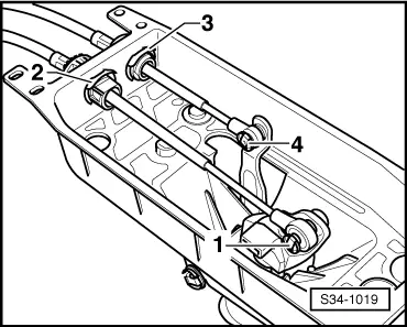
–  Attach shift cable and selector cable to shift housing with circlips -2 and 3-.
–  Press shift cable and selector cable onto shift lever and selector lever into shift housing (lock washers -1 and 4- are no longer available).
  S34-1019
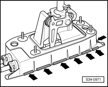
–  Install gasket and attach cover for shift mechanism by bending up the tabs -arrows-.
–  Install gearshift mechanism (Octavia II) → Chapter.
–  Install gearshift mechanism (Superb II) → Chapter.
–  Install gearshift mechanism (Yeti) → Chapter.
–  Setting the shift mechanism → Chapter.
  S34-0971

Summary of components - Control cables up to 10.06 > < Dismantling