skoda Workshop Repair Guides

Skoda Workshop Service and Repair Manuals

Removing and installing the exhaust gas temperature sender 1G235 > < Exhaust gas turbocharger with component parts - Summary of components
Removing and installing exhaust gas turbocharger
(Octavia II, Superb II, Yeti)
Special tools and workshop equipment required
t  Pliers for spring strap clamps
Removing
  Caution
In case of mechanical damage to the exhaust gas turbocharger, e.g. damage of the compressor wheel, it is not sufficient to only replace the exhaust gas turbocharger. In order to prevent consequential damage to the engine, perform the following tasks:
t  Clean all oil lines.
t  Change engine oil and oil filter.
t  Check air filter housing, air filter element and charge air pipes as well as charge air hoses for soiling.
t  Check all the air guides and the charge air cooler for foreign bodies.
If foreign bodies are detected in the charge air system, the complete charge-air routing must be cleaned and if necessary the charge air cooler must also be replaced.
  Note
t  Observe rules for cleanliness → Chapter.
t  Observe general instructions for charge-air system → Chapter.
–  Remove pre-exhaust pipe with diesel particle filter → Chapter.
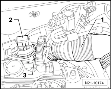
–  Remove air filter housing with air mass meter -G70- and intake hose → Chapter.
   
–  Remove -1- intake manifold, disconnect plug from position sender for charge pressure regulator -G581--2- at exhaust gas turbocharger.
–  Detach vacuum line -3- at exhaust gas turbocharger.
–  Remove fan shroud with radiator fans → Chapter.
  N21-10174
–  Disconnect plug connection -3- for exhaust gas temperature sender 1 -G235- and expose electrical cables.
  A23-10003
–  Release the fixing screw -3- from the charge air pipe, slacken the clamps -1 or 2-.
–  Release fixing screw -arrow- of charge air pipe.
  N15-10513
–  Detach the connecting hose -arrow- from the pulsation dampener.
–  Push the left charge air pipe as far as possible to the left.
–  Remove pulsation dampener, Position 21 → Chapter from exhaust gas turbocharger.
  Caution
The exhaust gas temperature sender 1 -G235- covers the top bolted connection of the support for exhaust turbocharger and must not be bent. For this reason it must be removed.
–  Remove exhaust temperature sender 1 -G235- → Chapter.
  N15-10517
–  Unscrew screws -1, 2- and hollow screws -4, 5- and remove the support for exhaust turbocharger with oil feed line.
  A21-10494
–  Remove connection pipes -A- to exhaust gas recirculation radiator.
–  Remove heat shield at exhaust manifold.
–  Screw out fixing nuts of exhaust manifold.
–  Remove exhaust turbocharger with exhaust manifold downwards, to do so slightly push the engine/gearbox assembly to the front.
Install
Installation is performed in the reverse order, pay attention to the following points:
  Caution
Before installing, check if the decoupling element of the oil return-flow line is not bent and therefore is not overstretched. If this is the case, microcracks might have occured which can result in leaks. If necessary, replace the oil return-flow line before installing the exhaust gas turbocharger.
  Note
t  Replace the gaskets, the sealing rings and the self-locking nuts.
t  Fill exhaust turbocharger with engine oil through the connection fitting of the oil feed line.
t  Observe the assembly instruction for hose connections with screw clamps → Chapter.
t  Remove oil and grease from the charge air pipes and hoses and from their connections before installing.
t  Secure all hose connections with corresponding hose clips.
t  Tightening torques: → Chapter.
–  Checking the oil level:
t  → BookletOctavia II.
t  → BookletSuperb II.
t  → BookletYeti.
  Note
After installing the turbocharger, run engine at idling speed for about 1 minute to ensure that oil is supplied to the turbocharger.
  N15-10443

Removing and installing the exhaust gas temperature sender 1G235 > < Exhaust gas turbocharger with component parts - Summary of components