skoda Workshop Repair Guides

Skoda Workshop Service and Repair Manuals

Testing the compression > < Install cylinder head cover
Removing and installing the cylinder head
(Octavia II, Yeti)
Special tools and workshop equipment required
t  
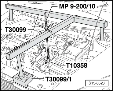
Supporting device -T30099-
t  Surface -T30099/1-
t  Support -T10358-
t  Sealant remover gasket stripper (bearing code GST, bearing article no. R 34402), manufacturer Retech s.r.o.
t  Cleaning and degreasing agent, e.g. -D 009 401 04-
t  Protective goggles and gloves
Removing
Requirements
l  Engine temperature should not exceed 35 °C, because the cylinder head could be twisted when slackening the screws.
l  The pistons must not be in TDC
Observe safety measures → Chapter.
Observe rules for cleanliness → Chapter.
  WARNING
Release pressure in the high pressure area of the fuel system → Chapter.
–  Drain the coolant from the cooling system → Chapter.
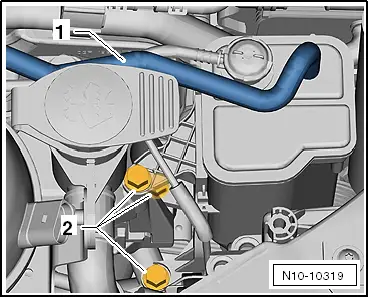
–  Remove coolant regulator housing from cylinder head.
–  Remove top timing case → Chapter.
–  Remove bottom timing case → Chapter.
–  Remove exhaust turbocharger → Chapter.
–  Removing the intake manifold → Chapter.
–  Fit supporting device -T30099-.
   
–  Unscrew the fixing screw for the gearbox and screw down the bracket -T10358- as shown. (The figure shows the version with the 1.4 ltr./90 kW TSI Engine; the hanger is identical).
–  Support the engine via the spindle in its installed position and slightly pre-tension.
  S15-0523
–  Disconnect the fuel feed line -1- and the cable to the activated charcoal filter -2-. To do so press the release buttons.
  WARNING
The fuel feed line is pressurized! Wear safety goggles and safety gloves, in order to avoid injuries and skin contact. Place cleaning cloths around the connection point before detaching hose connections. Reduce pressure by carefully removing the hose.
  N10-10317
–  Release the fixing screws -2- and remove the activated charcoal filter upwards.
  N10-10319
–  Unscrew screws -arrows- and remove engine mount.
–  Remove cylinder head cover → Chapter.
–  Remove the tensioning rail and the sliding rail of the timing chain.
–  Remove the roller rocker arms together with the balancing elements and lay aside on a clean surface.
–  Ensure that the roller rocker arms and the balancing elements are not mixed up.
  S10-0430
–  Release the cylinder head bolts in the specified sequence and remove.
–  Carefully remove the cylinder head.
Install
  S15-0289
Tightening torque of non-return valve -arrow-: 7 Nm.
Precondition
l  The pistons must not be in TDC
  Note
t  Remove the new cylinder head gasket from its wrapping immediately before fitting.
t  Treat the new gasket with the utmost care. Any damage will result in leaks.
t  There must be no oil or coolant in the blind holes of the cylinder head bolts in the cylinder block.
–  Stuff clean cloth into the cylinders to avoid any dirt getting in between cylinder wall and piston.
  WARNING
Wear protective gloves when working with sealant and grease remover!
–  Make sure that when cleaning the cylinder head and cylinder block no foreign bodies can get into the cylinder or into the oil and coolant galleries.
–  Carefully remove old sealant residue from the cylinder head and cylinder block using a chemical sealant remover.
–  Position piston of cylinder 1 to top dead centre and slightly turn the crankshaft anticlockwise again.
–  Position the new cylinder heads. The legend (part number) must be legible.
–  Insert the cylinder head. Pay attention to the centering pins in the cylinder block.
–  Insert new cylinder head bolts and tighten by hand.
  N15-10593
–  Tighten cylinder head bolts in the tightening order shown as follows:
t  Tighten all screws to 40 Nm.
t  Then, torque all bolts further to 90° (1/4 turn) with a rigid wrench.
t  Finally, once again turn all bolts through a further 90° (1/4 turn).
–  Insert the hydraulic balancing elements in the cylinder head and position the relevant roller rocker arm on the valve stem ends or balancing elements.
–  Install cylinder head cover → Chapter.
–  Setting the timing → Chapter.
Further installation occurs in a similar way in reverse order to removal.
–  Top up and bleed cooling system → Chapter.
  S15-0290

Testing the compression > < Install cylinder head cover