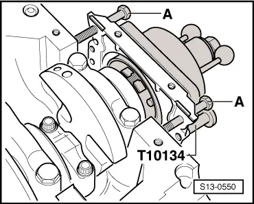
skoda Workshop Repair Guides

Skoda Workshop Service and Repair Manuals

Crankshaft > < Removing
Install
Install
  Note
t  
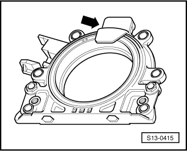
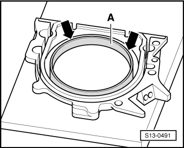
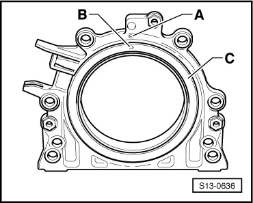
The sealing flange with PTFE gasket ring is provided with sealing lip supporting ring. This supporting ring is intended as an assembly sleeve and must not be removed before installing.
t  
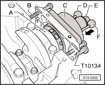
Do not separate or turn the sealing flange and rotor after removing them from the spare part package.
t  
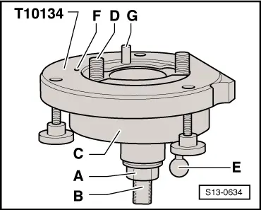
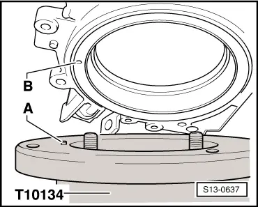
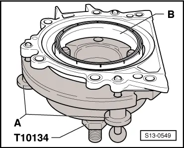
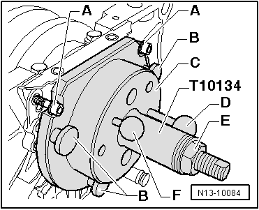
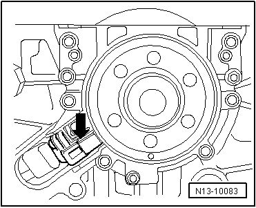
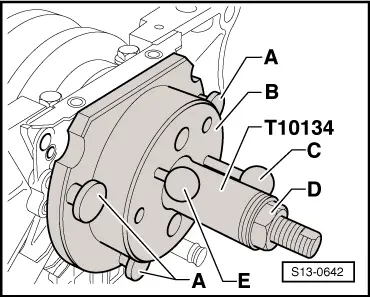
The rotor is given its fitting location by fixing the assembly tool -T10134- to the positioning pin.
t  The sealing flange and gasket ring form one unit and must be replaced together with the rotor.
t  
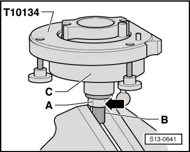
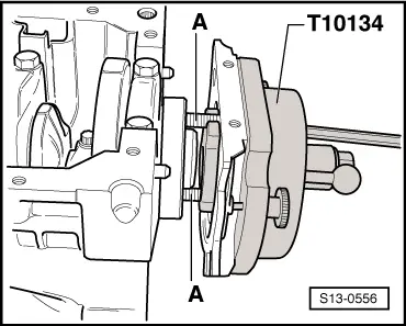
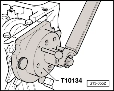
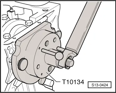
The assembly tool -T10134- is given its fitting location to the crankshaft by means of a guide bolt, which is guided into a hole of the crankshaft.
   
Assembly tool -T10134-
A - Hexagon nut
B - Clamping surface
C - Assembly cup
D - Allan screw
E - Guide bolts (with red handle - for fuel engine)
F - Positioning pin
G - Guide bolts (with black handle - for diesel engine)
A - Mounting sealing flange with rotor on the assembly tool -T10134-
  S13-0634
–  Screw the hexagon nut -A- right up to the clamping surface -B- and grip the assembly tool -T10134- on the clamping surface -B- of the threaded spindle in a vice.
  S13-0641
–  Remove the securing clip -arrow- from the new sealing flange.
  Note
Do not remove or turn the rotor from the sealing flange.
  S13-0415
–  Lay the front side of the sealing flange on a clean and level surface.
–  Press down sealing lips supporting ring -A- in -direction of the arrow-, until it rests on the level surface.
  Note
The top edge of the rotor and the front edge of the sealing flange must be flush.
l  The locating hole -B- on the rotor -C- must be flush with the marking -A- on the sealing flange.
  S13-0491
  S13-0636
–  Lay the sealing flange with the front side on the assembly tool -T10134- in such a way that the positioning pin -A- engages into the hole -B- of the rotor.
  Note
Make sure the sealing flange lies flat on the assembly tool.
  S13-0637
–  When tightening the knurled screws -A- press the sealing lip supporting ring -B- on the surface of the assembly tool in such a way that the positioning pin cannot slide out of the rotor hole.
B - Mount the assembly tool -T10134- on the crankshaft flange
l  The crankshaft flange must be free of grease and oil
l  Crankshaft is at TDC for cylinder 1
–  Unscrew hexagon nut up to the end of the threaded spindle.
  S13-0549
–  Screw assembly tool -T10134- with Allan screws -A- up to the stop onto the crankshaft flange.
  S13-0556
–  Screw in two M6x35 mm screws -A- by about 3 turns for sealing flange guide into the cylinder block.
  S13-0550
–  Move the assembly cup -C- by hand in the -direction of the arrow- until the rotor -B- rests on the crankshaft flange -A-. Subsequently insert the guide bolt with red ball -F- fully into the threaded bore of the crankshaft. If the guide bolt is correctly pushed in, then the handle has a distance of approx. 10 mm from the assembly cup -C-. This gives the rotor its final fitting location.
C - Pressing the rotor onto the crankshaft flange
–  Screw in hexagon nut by hand onto the threaded spindle until it rests against the assembly cup.
  S13-0423
–  Tighten the hexagon nut of the assembly tool using a torque wrench with adapter.
   Tightening torque: 35 Nm.
  Note
After tightening the nut to 35 mm there must still be a narrow air gap between the cylinder block and the sealing flange.
D - Inspecting the fitting position of the rotor on the crankshaft
  S13-0552
–  Unscrew hexagon nut -E- up to the end of the threaded spindle.
–  Unscrew two M6x35 mm screws -A- from the cylinder block.
–  Release three knurled screws -B- from the sealing flange.
–  Unscrew two Allan screws and remove assembly tool -T10134-.
–  Remove sealing lips supporting ring.
  N13-10084
The fitting position of the rotor on the crankshaft is accurate if there is a distance -a- = 0.5 mm between the crankshaft flange -A- and the rotor -B-.
  S13-0501
–  Position the steel striaghtedge onto the crankshaft flange.
–  Measure the distance between the steel straightedge and the rotor with a feeler gauge.
If the measured distance is less than 0.5 mm:
–  Press down rotor → Anchor.
If the dimension is correct:
–  Tighten the new fixing screws of the sealing alternately crosswise.
   Tightening torque: 10 Nm.
  S13-0638
–  Install engine speed sender -arrow-.
   Tightening torque: 5 Nm.
–  Installing the oil pan → Chapter.
–  Installing intermediate plate.
–  Install flywheel with new screws.
E - Pressing down the rotor
  N13-10083
–  Screw assembly tool -T10134- with Allan screws up to the stop onto the crankshaft flange.
–  Screw in three knurled screws -A- into the flange.
–  Subsequently insert the guide bolt with red ball -E- fully into the threaded bore of the crankshaft. If the guide bolt is correctly slipped on, then the handle has a distance of approx. 10 mm from the assembly cup -B-.
  S13-0642
–  Tighten the hexagon nut of the assembly tool using a torque wrench with adapter.
   Tightening torque: 40 Nm.
–  Again inspect the fitting position of the rotor on the crankshaft → Anchor.
If the dimension -a- is again too small:
–  Tighten the hexagon nut of the assembly tool to 45 Nm.
–  Again inspect the fitting position of the rotor on the crankshaft → Anchor.
  S13-0424

Crankshaft > < Removing